After a Twitter poll in which a grand total of three followers voted (still not as bad as the turnout at the local elections) it was decided I will attempt to repair my faulty oscilloscope. This requires the building of a new HV unit known as a 'tripler' and makes use of diodes and capacitors in a 'Cockroft - Walton' configuration. This will replace the sad, burnt out remains of the previous unit...
 |
| Burn marks aplenty |
In a nutshell, this 'ladder' of components takes the voltage at one end (say 2000V) and multiplies it up to a much higher voltage (6000V if the input is 2000V). So, not something to be flippant about since high voltage can kill.
While researching how best to approach this I came across a reference to a type 5502 oscilloscope - what I did was try searching for the reference that is on the top of the flyback transformer - and as luck would have it, the manual was available as a badly scanned, low resolution PDF file. A quick look confirmed that this was almost the same as my oscilloscope, but this model in the manual was a 20Mhz version, whereas mine is a 40Mhz version.
Closer inspection revealed that there were some significant differences. Most annoyingly, these were centred on the HV section of the main board where it appeared as if there was no potted HV marked tripler, rather just a bunch of diodes and capacitors. Whilst not a disaster, this did make me wonder if the values for those components in the manual would actually match my unit.
Then I had a brainwave. The model in this manual was the 5502, which is a the 20Mhz version. I wondered if the 5504 would have been the model number of the 40Mhz version. Google is my friend. Indeed, it is my friend forever now because searching for '5504 oscilloscope' lead me to a webpage that had a link to a manual. But was it the right one?
 |
| My Scope |
 |
| Is it a match? |
OH YES! Not only is this the correct manual but it also includes a list of components and a schematic for the HV tripler (which is actually a 'Three Stage Half Wave High Voltage Multiplier') which means I know what parts I need to order! That is, I believe, a bit of a result.
There are huge advantages to having the manual for this thing. Firstly, it gives me the correct specification for the parts for the HV unit. Second, it also provides a method of calibrating the scope on the assumption that replacing the HV unit is probably going to send it slightly off calibration. Finally, having the full instructions means I can make sure I am actually using this thing properly - assuming I can get it working again..
So, what parts do I need? Here's the bit of the schematic that's important:
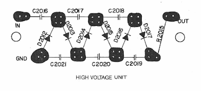 |
| Danger! Danger! High Voltage! |
So I need six high voltage diodes (10kV), six high voltage capacitors (1000pf, 10kV). Values are shown in the helpful list of components:
 |
| Certainly the oddest shopping list.. |
I have already ordered some diodes but I actually need to order a few more. There were five in a pack and I ordered them before I found the manual thinking I'd only need three (for a doubler) or five (for a tripler) - in actual fact, I would've always needed four or six but I did not spot that until too late... No worries.
The capacitors are about to be on order when I can find someone with the right values and can deliver sometime in the next week or so. In fact, I just found someone selling 1000pf 15kV caps. They'll do.
With a fair wind and the avoidance of World War 3, I should have all the parts by next Saturday (19th March).
I shall be building a voltage multiplier to take 2000V and boost it to 12000V.
What could possibly go wrong?
No comments:
Post a Comment