 |
| Video Signal - Single Field |
A little while ago my most excellent boss gave me his old oscilloscope. It's an Iso-Tech ISR440 which, from the limited information I have managed to find, is a brand from RS Components in the UK and it was made circa 1990(ish). So it's a good few years old but the display was nice and bright and it's just what I needed to replace the self-built kit (which is surprisingly good for its size), and the scope-meter donated by my other most excellent boss, but which has a problem of the screen contrasting decreasing all on its own... Some pictures of happier times.
 |
| Video Signal - Two Fields |
 |
| RAM Access |
Recently, during use, I noticed that the trace suddenly seemed to be very dim so I did what every good engineer might do. I turned the brightness up. After a few more days I realised that the trace was very, very dim and the brightness needed to be at full tilt to see the trace.
Hmmm. A problem may be developing...
Another few days went by and I had the scope on and it was working but then, all of a sudden, it wasn't. The power light was on but there was definitely nobody home.
 |
| Nooooooooo! |
After some attempted percussive maintenance (a couple of sharp taps on the top and sides) I realised that it was dead.
Those of you out there who know anything about CRTs, be they in TVs or oscilloscopes will know that they need large voltages to work correctly, typically anywhere from 6000V(6kV) to 18000V (18kV) depending on tube size and application. I had initially decided not to bother as I don't want my face burned off, and to put it down to experience. The scope is 30ish years old after all. But then I had a change of heart after watching a few youtube videos on scopes with no trace. Several seemed to indicate that a simple capacitor failure related to the drive circuit was enough to prevent a trace from appearing. If I can fix this with a simple cap replacement, that would be awesome!
Initial Testing
Normally, anyone trying this would need a schematic but this model has no documentation available online at all. There are a couple of mentions of it in RS Components notices of obsolete equipment but no manuals, no schematics, nothing. This makes things more difficult but not impossible.
The 'calibration' signal on the front of the scope still works. I can get a clear square wave at the right voltage which I can view on my 'kit' scope. So that indicates that there's a good chance that the power supply is OK.
Next, time to get down and dirty inside..
 |
| Show us your bottom |
 |
| And here's the top |
I found the main transformer where the power enters and tested the voltages at the point where they joined the PCB. They didn't really match what I expected but I suspect I was measuring them incorrectly. A quick poke around the board showed that the following DC voltage lines were present:
- 3.3v
- 5v
- 12v
- -12v
- 148v
I have to assume that these are OK as they look within the ranges expected in this type of equipment and, of course, I don't have a schematic..
 |
| Incoming mains transformer |
 |
| Bottom row of connections is the main power in |
Next thing. Assuming that there is power going in OK, what about the tube? Is voltage reaching the heaters in the CRT? After nervously switching it on with no covers on, the answer was proved to be, yes. A gentle glow was emanating at the end of the CRT where the control wires connect.
 |
| It's small but it's there |
 |
| Closer, closer, closer... |
Voltage is reaching the end of the CRT then. Next, there are a couple of neon lights on the main board which are used to reduce the voltage on the grids inside the CRT (massively oversimplified and possibly wrong explanation there). In any case, the neon bulbs remain off at all times. They should flicker slightly as the power is switched on or off but no response, Captain.
So now it's time to get that HV board out. As the scope is sat in its regular position the board is located on the right side of the unit or on the bottom if the scope is stood on its end. But before I go anywhere near it with a screwdriver though, I have to discharge the CRT. This is a well known, straightforward and terrifying procedure which involves attaching a cable to the frame of the scope (with a crocodile clip) then to a screwdriver (also crocodile clip) and then sliding the screwdriver under the Anode cap, ensuring that contact is made with the metal clips on the cap.
 |
| There be dragons... |
 |
| Pah. What's the big deal? |
I found out a few things while doing this. Firstly, the Anode cap is not as tight as the ones on other CRTs I've discharged (mostly old Macs) and this one popped out a little quicker than I thought. Second, it looked like there was no high voltage on the cap or the tube as there was no crack when I made contact with the metal contacts on the cap and the tube itself. Finally, I really hate CRTs.
Anyway. With that done I could now get on with the process of dismantling this thing. The next item was to disconnect the voltage connector at the back of the CRT. I knew I'd have to do this as some of the wires on the HV board linked directly to the connector and were already quite tight. This was easily done although I was very gentle as I did not want to break the neck of the CRT. That would be bad.
 |
| Neck board removed |
And now, to remove what felt like 100 screws and earth wires (actually more like 12 or 14 or so) and disconnect a billion connectors (more like 10 or 12 or so). I also had to remove the knobs on the timebase switch as this is mounted directly to the HV board. They were held on with a couple of grub screws that needed a tiny allen key. Fortunately my multi-screwdriver bit set had just the right size and they were removed easily.
Finally, I was ready to remove the HV board. Annnndd....I couldn't get it out. Three wires were soldered directly to the board and were stopping me from pulling out. One went to the front and was connected a BNC connector and the other two went into the neck board. These two were the -x and +x voltages for the electron beam. I carefully desoldered the three wires and noticed that, rather annoyingly, the pads on the x wires were lifting from the board. But I digress.
 |
| First wire to desolder |
 |
| -x and +x wires - brown wire with black sleeve is the -x |
But at least now, I could get the HV board out and have a proper look at it.
 |
| Ta-da! |
I took off the cover that was hiding the ominously labelled 'DANGER HIGH VOLTAGE' section of the board. Initially, I was looking for signs of a cap failure or, failing that, just an idea of what caps are involved in the circuit. But then I spotted something. Can you see it in the picture below?
 |
| Errr... |
Let's have a slightly closer look.
 |
| Are those burn marks? |
 |
| Eeek! They're burn marks! |
 |
| Why is it lumpy?? |
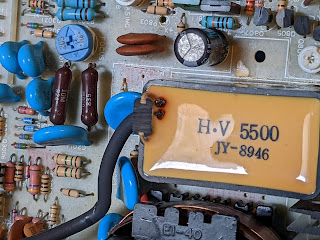
At this point I thought I would go for broke and desolder this component. The anode cap comes from it and I have since learned that it forms part of the 'flyback' arrangement for the CRT and is known as a 'tripler'. The key thing is that it increases the voltage to the correct levels for the CRT anode - probably between 7kV and 10kV. Let's get it off the board and have a look.
 |
| **** |
I think the phrase I am looking for rhymes with 'clucking bell'.
 |
| Holey smoke! |
 |
| Grey smear on the heatsink |
No comments:
Post a Comment