So, I'd been waiting for ages to get some time to sort out a Pi Zero version of the excellent Pi1541 which now supports the Pi Zero (surprise, surprise). I'd got as far as making a nice cable, I had the level converters, I wired it up and even installed the software. All I needed was a suitable Commodore machine to try it on and the only one I have is my trusty Plus/4.
Finally, I got the Plus/4 out of storage, plugged it in and... it didn't work.
To cut a long story short it looks like the PLA has died. So this project is on the backburner pending the arrival of a new, working PLA.
Now what?
Well, I had noticed the ripples in the Amiga universe regarding a somewhat unbelievable sounding project that would give proper, lag free HDMI output on an Amiga A500, all for the price of a small adapter board and a Raspberry Pi Zero.
Interesting.
Of course, I had to get one of these being a bit of an Amiga nut (it says so in the tiny bio over there ->). The gerber files for the adapter boards are freely available so I could have just used one of the many PCB prototyping services to generate a small run of brand new boards but I didn't want the hassle. As I am no longer what you would call 'young' I also didn't want the hassle of trying to solder the small number of SMD components on to the board that make the magic happen.
In this case, eBay came to the rescue as I found someone who already had some adapter boards, with SMD components already installed and all for a very reasonable price. I won't put any links here as it's eBay and you can search it out for yourself. So there.
 |
| SMD - Too small for my ancient sausage fingers. |
 |
| Look at the backside on that. |
The only things missing from the board I received (very quickly - nice one) was the pin headers, a chip socket and the 40 pin socket to accept the Pi Zero. I already had a chip socket and a 40pin socket header so I just needed pin headers. And eBay came to the rescue again. Yay!
Finally, I already had a Pi Zero which was originally intended to be the Pi1541. No longer.
Quick summary - this board fits into the Denise socket and the Denise chip fits into the adapter board. The Pi Zero fits into the 40 pin socket. Plug in a HDMI cable. Bob's your Uncle (well, he's my Dad actually).
 |
| All present and correct. |
Building the board was a bit more of a journey that you'd think so I shall try to put everything here in order so that you don't have to struggle if you do one of these. It's worth noting that there are plenty of videos of people building these things on youtube, including the excellent Jan Beta who had similar issues to me.
So, first, solder in the Denise/Super Denise headers. This should be a header with three pins and, as I found out, it should be right angled. The one I put in was actually straight and I didn't realise that this was an error until later. If they are straight, they stick up (down?) too far and will stop you inserting the completed unit into the chip socket on the A500 motherboard. I didn't have any right angled headers so I had to use a frightening amount of force to bend the straight pins I had install to 90 degrees. Not a fun 30 seconds and not recommended. If you are only using this on a machine with standard Denise or only with a Super Denise you could obviously just short the correct holes together instead of fitting header pins.
Second, solder in the pin headers. These are the pins that will fit into the Denise socket so I made sure to get the narrow, turned pin versions that are less likely to knacker the socket on the motherboard. Make sure you solder them in the right side. The 'soldering' side is the same as the side where the SMD components are with the long pins on the other side. To get them straight I actually inserted the pins with the board into a 48 pin socket so the whole thing was held firm while soldering. This worked quite well but was a bit nerve racking to remove it once I'd finished the solder work. Perhaps I should have used a bread board..
 |
| Headers soldered using a socket as a guide |
Next, solder the chip socket on to the adapter board, which is where Denise will eventually sit. This goes on the opposite side to pin headers so you're soldering the legs on the opposite side to where you soldered the pin headers. Make sure you line up the notch in the socket with the notch on the silkscreen on the board.
Now this is where I had a little wobble because the solder joints from the pin headers actually foul one side of the socket, leaving it a bit skew whiff. To make sure this wouldn't cause any problems later, I carefully raised the other side of the socket so that it sat on the board as level as I could get it, even though this left it standing slightly proud and didn't leave much of the legs sticking through the holes. My socket was a cheap one. Other, higher quality ones might not have this same problem.
Now, solder the 40 pin socket on. Nothing controversial here. Just try to get it on flush to the board and straight.
 |
| Jumpers, Headers and Socket soldered in. |
 |
| And from the other side. Looking good. |
There is an additional place on the board for another two pin header which will accept a switch. This is, apparently, intended to force resolutions in certain circumstances but is optional. I left it out.
So, in summary the order of soldering on the adapter board should be:
- Denise jumper (right angled!)
- Header pins (the ones that'll go into Denise' socket on the motherboard)
- Chip socket (for Denise)
- 40 pin header socket (for Pi Zero)
And that's it for soldering. Now all I had to do was plug it in and test it.
Installation is very simple. First, the software needs to be put on to the Pi SD card. I freshly formatted the 8Gb card that I had intended to use for the Pi1541. This is massively over the top as the actual software is a few megabytes as it 'bare metal' i.e. no operating system, just the necessary software to do what's needed. This can be grabbed from here. Just grab the latest release and copy the contents of the zip file to the SD card. That's all you need to do.
Next. Find an A500 and get it's top off. (Mine is just a bare A500+ motherboard I use for testing.)
 |
| Oh, Mother(board). |
Then, find Denise and gently remove her from the socket and put her to one side.
At this point I pushed the Pi into the 40 pin socket on the adapter board.
 |
| Top view (no Denise yet) |
 |
| Bottom view. |
Take Denise and gently press her into the socket installed on the adapter board.
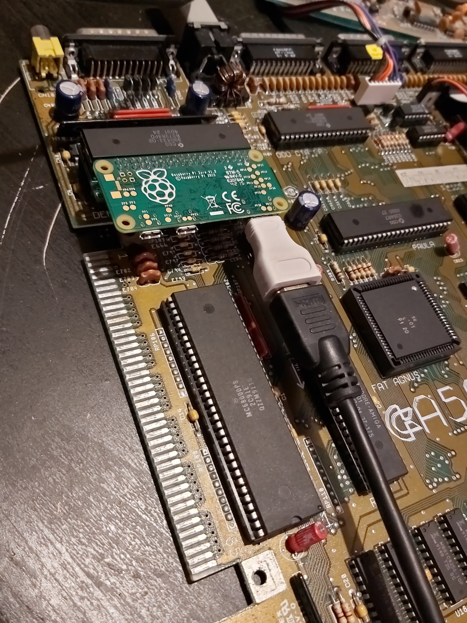
Then, finally push the whole assembly carefully into the now empty socket for Denise on the motherboard. It should now look something like this:
 |
| Installed - Wide(ish) Angle |
 |
| Close Up. |
 |
| From the side. |
Right. Denise is in place. We are now ready to test. Fetch me your finest HDMI cable!
 |
| Standby for action. |
Does it work.....? Of course. ;)
 |
| DMA Design. What could this be? |
 |
| Oh, yes! More Lemmings. |
 |
| Title Screen. |
 |
| Level 1 Lemmings. |
This board is AWESOME. If you have an Amiga A500 you HAVE to get this board. It should be a crime to use an A500 without this board. It is just amazing, the pin sharp quality of the picture. These photos just don't do it justice. And for the sake of a simple board and a Pi Zero. WAY cheaper than loads of the current solutions out there. Unbelievable. Just freakin' amazing.
Get one of these for every Amiga A500 you have. What are you waiting for??
But, wait a minute....
Although this version of the board allows you to select either Denise (OCS) or Super Denise (ECS), it still only supports the OCS screenmodes. But for most users playing games this should not be an issue.
And another thing. I had hoped to show this working on that stupidly huge Sony 40 inch TV that lurks in my workspace, threatening to make my desk collapse with its weight. But it doesn't work. When the screen from the Pi initialises it selects a bizarre resolution that results in a squashed picture with glitches across the screen. I suspect that the TV is sending something odd down the HDMI cable and confusing the Pi. The TV is very old even though it is HD. As a result I will need to test on a few other TVs.
But why haven't you got one for you A500 yet? Go on. Get to it. Go. NOW.
 |
| Naked Amiga - A thing of beauty. |