Sunday, December 11, 2016

Amiga A500 + Motherboard - Part 5 - The End

Oh dear.

A black screen.

Having been stopped dead in my tracks by the black screen of despair, I stopped and had a long think about what to do next. I could throw the board in the bin after salvaging the custom chips etc. Or I could run around the room waving a ladle and screaming 'the transmission of the Austin Allegro is mounted transversely to reduce gyroscopic torque'.

Fortunately I decided to go back to basics.

Check the traces. Again.

First up, the 68000. As the screen is black and black normally means a dud processor, I did two things. I put in a spare good CPU but still got the black screen. Then I checked all of the traces from the 68000 out onto the board. No problems found.

Next, I went back to the logic section. I tested all of the pins on U10. All traces good. Then U11 and 12. All traces good. Then, finally U13. All traces good BUT I noticed something that looked odd. A trace runs up to R111 (which was fine) and then from R111 to pin 25 of Gary. I measured this too expecting a resistance of 68 ohms. I got nothing. No continuity from the end of the resistor to pin 25.

This track is only about 5mm long so this was surprising and I was sure at some point I had checked this previously. Time to get a picture (or two)..

Is that a break?

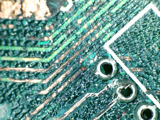
After examining this I thought it was a straightforward break in the track. The green line through the trace looks like it is a break but this was a red herring and was actually a piece of the solder mask still in place.

Let's look a bit closer at the pad...

Well, there's your problem...

Ah. That looks like a bit of an issue. The track has disappeared from the point at which it should join the pad. I suspect what has happened is that removing the temporary resistors that I previously installed defeated the few specks of copper that were left of this trace. A proper clean and new picture shows it a little more clearly. The dull circle around the edge of the solder is basically bare substrate.

Track broken at pad - oh dear

To repair it I put a blob of solder on the leg of the resistor and dragged it across to the track. Relatively simple if not the neatest.

Track now present

New solder track close up

So, does this fix it?

NO. But we're now back to a green screen. This is the equivalent of getting the first 'chug' out of an ancient engine that's on the verge of starting for the first time in years..

After having another think about the basics again and, just for a laugh, I decided to re-seat all the chips including Agnus. Would you believe, as I removed Agnus, a chunk of corrosion fell out of the socket which was presumably accidentally inserted as I put the chip back into the new socket. A salutary lesson in keeping everything clean and tidy if ever there was one.

Back to the board. Does it power up and will it get past the green screen?


So there you have it. Another A500+ motherboard saved from the indignity of spare parts (or worse).

This board will eventually get a floppy drive and keyboard (and maybe an new expansion connector too) so I can test that it ALL actually works but, for now, I am overjoyed that I managed to get to the boot screen,

To everyone out there with an A500+ motherboard in this condition, keep at it. If I can do this, then so can you!

Here's a couple of pics of the success:

The recovering patient

The glorious purple screen
A list of parts used:

Resistors:
  2 off 28 ohm 1/4 watt
  1 off 47 ohm 1/4 watt
  3 off 68 ohm 1/4 watt
  2 off 1K ohm 1/4 watt

Capacitors
   1 off 10nf ceramic disk (not quite as original but OK)

Chips
  2 off 74LS244
  2 off 74LS373

Sockets
  4 off 20 pin DIP sockets
  1 off 84 pin PLCC socket
  3 off 36 pin sockets sacrificed for their pins for Gary and Paula (their loss will be remembered)

Misc
  Lots of solder
  About four inches of green wire wrap which I had lying around

Time
  Lots but the total is irrelevant if I can keep bringing them back from the brink...


Thanks for reading. 

Friday, December 09, 2016

Amiga A500+ Motherboard - Part 4

Standby for action.

First, that broken track. I wasn't happy with the 'temporary' repair as it looked more like I'd thrown the wire at the board in the vain hope it would stick. One touch of the soldering iron and it was gone quicker than my wages the day after I get paid...

The permanent repair is, to be fair, pretty much like the old one but with a bit more care. I don't have any fancy replacement PCB copper traces as these are monumentally expensive and this is, after all, a bit of a hobby and not my profession. More's the pity as I'd love to spend all day fixing these things. Anyway, the track is fixed, on to the next thing.


Can you see the join? (Just to the left of the socket)

Resistors. Nice and cheap from Tandy in the UK. It's a simple job of desoldering the old ones (including the temporary replacements I installed that may or may not have been the totally correct values) and then inserting the new ones. One advantage with new resistors is that they have nice long legs which makes it easy to get them into the board and then, by folding the legs out (or in if you prefer) underneath the board, they remain in place. This means you can get them all into the board in one go and solder them all in one go. The excess legs just need to be trimmed when it's done.


Folding the legs over 


Resistors Replaced - and now correct values!

Next.

Sockets. Each of these sockets cost 15p. Some purists may say the 500+ never came with sockets so why put them in now when a) they could cause connection issues that wouldn't happen if the logic chips were soldered to the board and b) it's a bit late. Well, these logic chips are still relatively cheap, but I'd much rather lose a total of 60p on sockets rather than the few quid I spent on the chips themselves if the board is beyond repair. Did I also mention I'm a bit of a cheapskate? Monetarily efficient is what I prefer to think. :)


New sockets

From the photo above you'll also notice something is missing. The expansion connector was too far gone to be useful. It wasn't the worst I'd seen but for the sake of a few quid for a new one it wasn't worth the pain of trying to clean up the old one. New connectors are available still (which is more than can be said for the female A1200 expansion connector) but I won't order one until I know this board is fixed.


Sockets flush with the board

A big hint for anyone starting out with soldering this type of component, be it socket or multi pinned chip. Hold them in place and solder opposite corners before you wade in and do the whole lot. If you don't your socket will end up at a funny angle and won't be flush with the board. I used a piece of masking tape on these which worked well. On my personal A500+, which I repaired a few months ago, I failed to do this and as a result there is a 74LS244 that appears to be making a break for freedom as one end is significantly higher than the other. Ooops.

Finally, I re-instated a link wire that I'd put on from one of the vias near the expansion connector to the jumper near the battery, to fix a potential additional track issue.


Link wire added

So with the sockets in place and the resistors now the correct value it's time to get the chips in this board and plug it in.


Can we get past the green screen?

I recorded the moment for posterity. (Do I really sound like that? Crumbs.)


Monday, December 05, 2016

Amiga A500+ Motherboard - Part 3

A short post this time.

If this were a film, this would be the point at which everything goes wrong for the hero but then turns around at the last minute. Racing to save the heroine, delayed by the evil bad guy, he loses her seemingly forever only to be reunited in a climactic final act which results in the bad guy dying and the good guy gets the girl forever.

Sadly, this part of my adventure involves a multimeter and a lot of traces. A lot of traces. Continuity checking is dull. I checked all of the traces from Agnus. I checked all of the traces through the logic section.

So many traces.... 
I Quit! (Not really)


I still have to check all the traces from Gary but I shall save that until I feel like shoving a multimeter probe in my ear...

On the plus side, the postman has been! Yay!

A500+ Essential Supplies

I would have ordered from one of the larger suppliers but due to their lack of stock or extortionate postage charges for small orders I went elsewhere. I ended up ordering from Tandy electronics which is the reborn UK version of Radio Shack. I have no idea whether they have any connection to Radio Shack now but their stuff was pretty cheap, they had most of the bits I needed and they only charged £1 for delivery.

Anyway, I will be fitting sockets and resistors etc when I  have a few spare minutes. Other than repairing a couple of broken traces, I really don't know what else there is to do before I start poking it with a hot stick again...


Saturday, December 03, 2016

Amiga A500+ Motherboard - Part 2

So, I managed to replace both Paula and Gary's sockets by re-cycling the plastic frames from the original sockets and replacing the pins with new ones pinched from new sockets that had the wrong number of pins. This was particularly tedious and shall not be repeated. I will order new sockets if there's another time...

On to more pressing matters. Does this board now work?

No. Black screen. Still. Bugger.

Right. After poking around a bit I removed U12 by carefully cutting it off the board. Then I decided to install a temporary socket made up of off-cuts of my Paula/Gary escapades. This would enable me to install a replacement chip to see if it was just a simple logic chip replacement required. While I was there I also noticed a bit of a problem...

Is this a broken track I see before me?

Yes.

A track had broken, most likely due to my cleaning efforts which, from the state of the board, looks to have dislodged a piece of the substrate which was probably damaged by the battery leak. This has left a small but significant 'pit' which obviously made it easy for me to catch the metal track as I continued cleaning. This is no big deal and I installed a temporary repair just while I carried on troubleshooting. This was a tiny sliver of wire, soldered across the two ends of the broken track to form a bridge. Unfortunately I forgot to take a photo but, as I am bound to say, it looked like new*.

*did not look like new.

Anyway. At this point I thought I should check all the tracks from Gary through to the logic section seeing as Gary took the brunt of the corrosion. All was OK except for one track. For some reason I could not get continuity from pin 2 of Gary to the 'north' side of R102. I thought that this might be due to corrosion on the solder joint of R102 so diverted off for a couple of hours to de-solder all of the resistors and capacitors in that area.

De-soldering this components was easy. Except when they disintegrated. Like R102. And R111. Oh, and R114. And, in fact, most of the resistors in the two little banks of components located below Gary on the motherboard.

I think the phrase rhymes with 'clucking bell'.

To cut a long story short, I scraped together most of the resistor values I needed and cobbled together a couple of bodges (resistors in series) to make the values I didn't have. New resistors are on their way but I haven't got them yet...

Temporary Resistor Repairs

Then, once I'd finished faffing with resistors I turned my attention back to the non-continuity of the track from pin 2 of Gary. Even with the new soldering in place, there was still no joy so I resorted to a short jumper wire to get around the problem. It's fairly discrete and I suspect I will leave this one on the board as it is not visible when the board is installed and does the job quite nicely.

Jumper on Gary

With all this done it was time to try and plug him in again.

Does he work? No. Green screen. BUT that is an improvement and shows we're getting there. Green screen is shown when there is a problem with the chip memory. It can be caused by a multitude of faults but the most common are a bad memory chip, bad logic chips or a broken Agnus.

I have ordered new logic chips (74LS244 and 74LS373) as they are the cheapest and simplest to replace and they should be here early next week; also included should be the resistors and some sockets for the logic chips. If they don't make any difference and I end up having to scrap the board at least I get to take back the new chips.

In the immortal words of The Carpenters, "Please, please, Mr Postman (Why's it takin' such a long time?)"...

Wednesday, November 30, 2016

Another A500+ Motherboard - Part 1

So on the Amiga Facebook pages, a rather nice chap (hi Russell!) let me have an A500+ motherboard for pennies. This board, as per the majority of A500+ boards, has battery leak damage.

Green edge connector

This does not look good

Curse you Varta!

So, anyway. A quick power up and all I get is, rather unsurprisingly, a black screen. This would normally mean a CPU failure but given the extent of the battery damage, this is a bit meaningless.

First things first, I removed all the removable chips to check for damage to the sockets. Again, as is fairly typical with these things, the Gary socket was toast. A connector in the socket had already disintegrated due to the corrosion from the battery leak and Gary himself was looking a little worse for wear.

Alas, poor socket...
This will need replacing. The picture doesn't really show how green the contacts are across the whole socket.

On to Paula. Oh, dear. The bottom half of her socket is almost as bad as Gary but the top looks OK. This will still need replacing though.,.


Even Agnus did not escape unscathed. There were telltale signs of green on her 84 pins too which did not surprise me (no picture I'm afraid) so, as I precaution, I will replace her socket as well.

The other chips faired rather better. The two CIAs, Denise, the ROM and CPU were all unscathed so no socket replacements needed for these. It looks like I will need to replace at least one, possibly more of the logic chips that are in the are of the acursed battery. The chip U12, which is a 74LS244, took the brunt of the leakage. Fortunately, I have one of these in my box of bits. I don't have any others though, so I'm hoping everything else can get away with a bloody good clean.

First task, remove the Gary socket. Normally, I would just cut the old socket off and then de-solder the pins but, for some reason, I decided to be a bit more careful and I'm glad I did. Once I had the socket off I could check for any further damage (there was a little bit) and try to clean any other corrosion up.

Gary socket gone - some cleanup works carried out.
It was at this point I realised I had no sockets of the same size as Gary's (or Paula's). I did have some smaller sockets with the same style of pins so I hatched a cunning plan. I would clean up the plastic frame from the original socket and remove the pins from the small socket and place them in the big socket. This was a lot less fun than it sounded.

Half Completed Gary
Once I had replaced all of the pins I realised that I would have to do the same again for Paula. But that's for next time...


Friday, November 25, 2016

Sadstick 2 - El Cheapo

The second of my 'additional' joysticks is the cheapest of the cheap. Cheapo McCheap of Cheapland could not have made this any cheaper if he tried (even on a particularly cheap sort of day).

Did I mention it's cheap?

It worked when I plugged it in to my Amiga but the down direction was a bit sluggish and intermittent. After I unscrewed the one screw in the base it became obvious why and I thought it would be an easy fix.

Either a super ingenious enclosure or it's cheap.

The switches in this stick are formed from a piece of spring metal with four lugs cut out and bent upwards. As the joystick is pushed, the base of the shaft pushes a strip of metal against the lug, making a contact. The 'down' contact just needed to be bent a little bit closer to the metal strip. And then it fell off in my hand. Bugger.

Spring Metal Switches - Cheap

What I ended up doing was using a long bolt and some nuts to make a riser from the base. By drilling a hole for the bolt and then inserting the bolt through the hole, a contact was made to the metal. I added a piece of copper from an old piece of Amiga A500 edge connector I had and screwed that onto the top, bending it slightly so the it was roughly the same location as the lug had been previously.

Just call me MacGyver
My heath-robinson switch


I did have to remove part of the base retainer to make my mod fit.


The handle has no components other than two plastic switches that push down a plastic 'stick'. This presses down onto another piece of (cheap) plastic that then activates the fire button switch. Incidentally, the handle spins round on this joystick but as far as I can tell, there is nothing stopping it nor was there ever anything to stop this. Perhaps they were relying on the friction of the springy rubber block in the base to stop rotation but it doesn't work.

So there you go. My mod fits after a bit of butchery with a craft knife and, yes,it does actually work. If only it weren't so CHEAP.


Saturday, November 19, 2016

Joystick Sadness (Sadstick?)

A few weeks ago I spotted a job lot of three joysticks on eBay for a very reasonable price. I was only really interested in one of them, and at the price I paid, the other two were a bargain.

Or so I thought.

The first of the additional sticks was a Cheetah Annihilator. If you are interested in retro gaming in any form then you will probably already know that this particular joystick could be described as the worst joystick in the history of mankind. If this was the last joystick in existence and I had to choose between the eternal fires of Hades or playing Sensible Soccer for an hour with this joystick then I'd be reaching for the suntan oil.

Imagine my (non)surprise when I realised it was broken. The handle didn't centre properly, the fire buttons on the top of the handle didn't do anything and the handle itself wasn't screwed together properly. Once I undid the screws in the handle it became apparent why. The previous owner had deliberately screwed it together in such a way as to grip the shaft of the joystick (no sniggering at the back) thereby semi-concealing the fact it's buggered.

The second joystick is very much an el-cheapo generic joystick from the cheap end of cheapo land. This one at least seemed to make no pretence at being anything other than cheap. Did I mention it's cheap?

I tested both of them on my Amiga and, sure enough, the fire buttons didn't work on the handle of the Annihilator but the base fire button did. The directions all worked but nothing could hide the sagginess of it. El Cheapo worked but the shaft twisted rather unnervingly but that's for another post.

So, do I bother doing anything with the Annihilator? Of course. 

Opening the handle revealed two wires connected to two random pieces of metal. Also inside was a 'z' shaped piece of black plastic and another chunk of the interior. After puzzling over the bits for a while it suddenly became obvious what I needed to do. Bin it...just kidding.

Comprehensively Broken

The two pieces of metal formed the 'switch' for the fire buttons and the 'z' piece held them in place. The only snag was that one side of the area that holds the 'z' piece had snapped off. To solve this I used a tactic normally reserved for large, heavy parts of Warhammer models. PIN IT! Basically, drill a hole from the exterior of the handle through to the inside. I actually did two holes. Then, superglue the broken piece back where it should be and let it set. Once set, I got the drill out again and extended the two holes into the superglued part. Finally, two pieces of stiff wire (a paperclip) were cut to length and superglued into the holes and left to dry. Job done.


Two tiny holes betray the pins

Re-instating the switch was straightforward after that. The only tricky bit was ensuring that the pieces were the right way around. The way the switch works is this. If the top button is pressed the button pushes the spring metal down onto the other piece completing the circuit. If the trigger is pressed the the button presses the metal where it makes contact with the other piece, completing the circuit. Cheap and nasty.

Next up, in the base, the switches used for the directions are of the 'dome switch' type. These are the same as used in the original QuickShot and QuickShot II joysticks. In this case they were covered in a huge sticky sheet of clear tape that was also covered in what looked like sawdust. I had to remove the tape (yuk) and carefully take the domes of the sticky side. I cleaned them with isopropyl alcohol and re-attached with a few small pieces of sellotape. Easy. (Apologies there are no photos of this - phone camera let me down.)

The next problem was that the handle just rotated around the shaft because the plastic lugs inside the handle which normally slot into the joystick shaft had snapped off. This was solved relatively easily with a couple of bolts. I drilled a hole on each side of the handle and inserted bolts long enough to slot into the shaft. 

New anti-rotating bolt fitted


Finally, how to make it a bit less sloppy. This was more difficult but I had an idea of using a spring of some sort under the shaft. As luck would have it, I had a few single battery boxes used in small projects. The spring contact from one end of one of these boxes was just the right size and strength to fit under the main shaft. The result was more than acceptable and a darn site better than it was originally. Again, apologies for the lack of photos on this bit - I did it at the same time as the dome switches and, for some reason, no photos came out..

So for this joystick, the only signs of anything being 'different' are a couple of tiny holes on the handle near the fire buttons, and what looks like a couple of screw heads at the bottom. A small price to pay to make it work.

All repairs done - re-assembly in progress

Re-assembly complete and all tested

It's still a steaming pile of crap though...


Tuesday, June 21, 2016

A1200 Capacitor Trouble (again)....

So on the A1200 that I repaired the other week, I noticed a very slight flicker in the video output. It wasn't much but it was noticeable. It looked like the colour 'green' would disappear for a split second and then it would come back.

Strange.

I took the motherboard out and had a good look over the topside. Nothing out of the ordinary but I think that it definitely needs to be re-capped. In any case, there's nothing obviously wrong on the top.

Turn it over and look at the back. My attention is immediately drawn to this:

Ouch.


Holy crap. Another failed capacitor... This is a general power de-coupling cap that has clearly failed in a fairly spectacular way. I'm surprised I didn't see this when I did the previous repair but, to be honest, it could've happened after I did that.

Anyway, as it happens, I have a few of these value SMD caps in my box so I just replaced it:

Shiny.
Having put everything together, I plugged the A1200 back in and switched it on. This is what I got:


Now, I may not be an expert electronics engineer but this does not look like an improvement.

I dug the board out again and got the USB microscope on it for another survey, this time I was looking for ANYTHING that might look out of the ordinary. It didn't take long...

These two resistors have been replaced by someone:

361? 360 ohms? Are you sure?
According to the A1200 schematics for Revision 1 type boards, these resistors should be 2000 ohms, not 360 ohms.


R217 is very badly soldered and looks like it has been messed with:

 Bad Solder Joints

R345 has been replaced:

681? 680 ohms? Are you sure?
According to the A1200 schematics, R345 should be 22,000 ohms. Yes, that's right, someone has replaced a 22K ohm resistor with a 680 ohm resistor. What the hell? If anyone has any idea why somebody would do this, feel free to comment below.


 This one (and another nearby - close to the op-amps for the audio) have also been replaced:

Correct - but REALLY badly soldered..
This last one (and it's pair) are part of a known fix for the audio on these earlier models. The original schematics had these at 1.5k ohms but that value is too high for the op-amps and the sound comes out distorted. 681 - or 680 ohms is the correct value. Soldering standard sucks though..

Finally, this:

Caps
This little group of three 1206 size components are capacitors. They should all be exactly the same as they are part of the de-coupling circuits on the video encoder, with one capacitor each on the Red, Green and Blue inputs. So why are there three different colours and why are they all soldered differently? Bottom one looks like factory, second one up is a reasonable manual attempt and top one has way too much solder on the right side. Could this be the cause of the video problem?

Fortunately, these are all 22nF which just so happen to be the only value of SMD caps that I have (and was also the same as the one I replaced at the top of page!). So, out came the soldering iron again. And now we have this:

More new shiny...

And that completely cured the video problem. Rock solid. I left Frontier playing its demo for nearly six hours and no problems. Another great result.

Just waiting for the 'real' caps to arrive so I can do a complete job on this A1200 now. :)


Wednesday, June 15, 2016

The Scarlet Amiga - Part 2

Sooooo. The Scarlet Amiga is working. It's a KS1.3 early(ish) A500 with a Samsung keyboard, a tidied up A501 half meg memory expansion and, following a lot of careful calibration, a working floppy drive. But we still have that awful sloppy red paint to deal with.


Following a few test scratches, the paint has two or three distinct layers. On the top is the red oil based gloss paint. I suspect that this is the same as some might use to paint skirting boards. Underneath that is a softer white-ish layer that I think may be some sort of spray paint, presumably used as an undercoat. In some areas there is also a dark green 'smudge' of what might be paint but could equally be wax crayon...

I googled 'remove paint from plastic'. One suggestion was to use vegetable oil on it, which should lift the paint from the plastic without causing any damage. I did actually try this as it would be non-destructive and if it worked would have been very cheap.

It didn't work. It just made the case oily.

Next up, isopropyl alcohol. This was a long shot as it's more a de-greaser than a paint remover.

That didn't work either. It just made the case shiny.

Next. Nail varnish remover (acetone basically). Mrs Crashed has (or had) a bottle of purple nail varnish remover which, to be honest, was a bit stronger than I anticipated. I put some across the top part of the case, near the AMIGA logo and within 10 seconds the paint had shrivelled and cracked. A quick scrape and a hug swathe of red paint was gone. BUT, where the acetone touched the bare plastic, the plastic started to melt and deform (she puts this stuff on her finger nails??) so, despite the promising results, I didn't continue with this.

By now we have a case that looks like this:

And so it starts...

More work has been done here - mostly around the inside of the keyboard

While trying to pick out the Amiga logo my hand slipped and, despite my best efforts, I failed to injure myself but I did put a large scratch in the paint. It was immediately apparent that large areas of the paint could be scraped off relatively easily using a handy scalpel with a flat square blade. This is the result of a couple of nights of scraping:

Getting there....

A smaller blade allowed me to get into the vents to some degree and soon, almost the entire top was back to an almost normal colour. A few more nights scraping and we've reached this point.


Vents waiting to be cleared


Almost done...


Fun fact. Do you know how many small ridges there are on the back of an Amiga A500 case? Seventy five. SEVENTY FIVE. S E V E N T Y  F I V E. Each one had to be scraped out by hand. 


It took over a week to get all of the solid red paint out of those ridges. If I'm honest, had I started by doing these ridges first it would have gone in the bin and I would've been searching ebay for a new case. But that would be cheating. :)

Red Gloss GONE
I realised some time ago that this case is not going to be suitable for selling. Even if I'd managed ti get all the paint off with no scraping or melting plastic, it was still in relatively poor condition.  Anyway, after all the effort I have put in I have decided that I will keep it for myself. 

There is still a lot to do on this case before I consider it finished. I intend to sand it down to remove the last bits of white/red paint and then I shall look at polishing it. This means it will lose it's customary patterned finish but, what the hell. It's my Amiga. :)

More updates soon..