So here it is:
 |
| "What's in the box?!" |
 |
| Oh. My. Goodness. |
Let's have a slightly closer look at the board and the extent of that damage. If you are of a nervous disposition, look away now.
 |
| Argh! The Horror! |
I can safely say that this is by far the worst A500+ motherboard I've had on my bench. The battery acid has spread from the end of the battery and engulfed U12, U10, Agnus and who knows what else. It really is pretty bad. Have I met my match?
First things first. Gary. What does the socket look like? Bizarrely, Gary was untouched. This is really unusual and could indicate that this A500+ was stored standing on its side.
OK. So, on to Agnus. Oh. Dear.
 |
| Looks bad. |
 |
| Yep. It's bad. |
So, a new socket required. The actual Agnus chip was OK and just needed a bit of a clean. The chip also had a chunk of the printing on it's top removed, presumably by the action of the battery acid...
 |
| Printing wiped from Agnus (Taken before I removed the chip) |
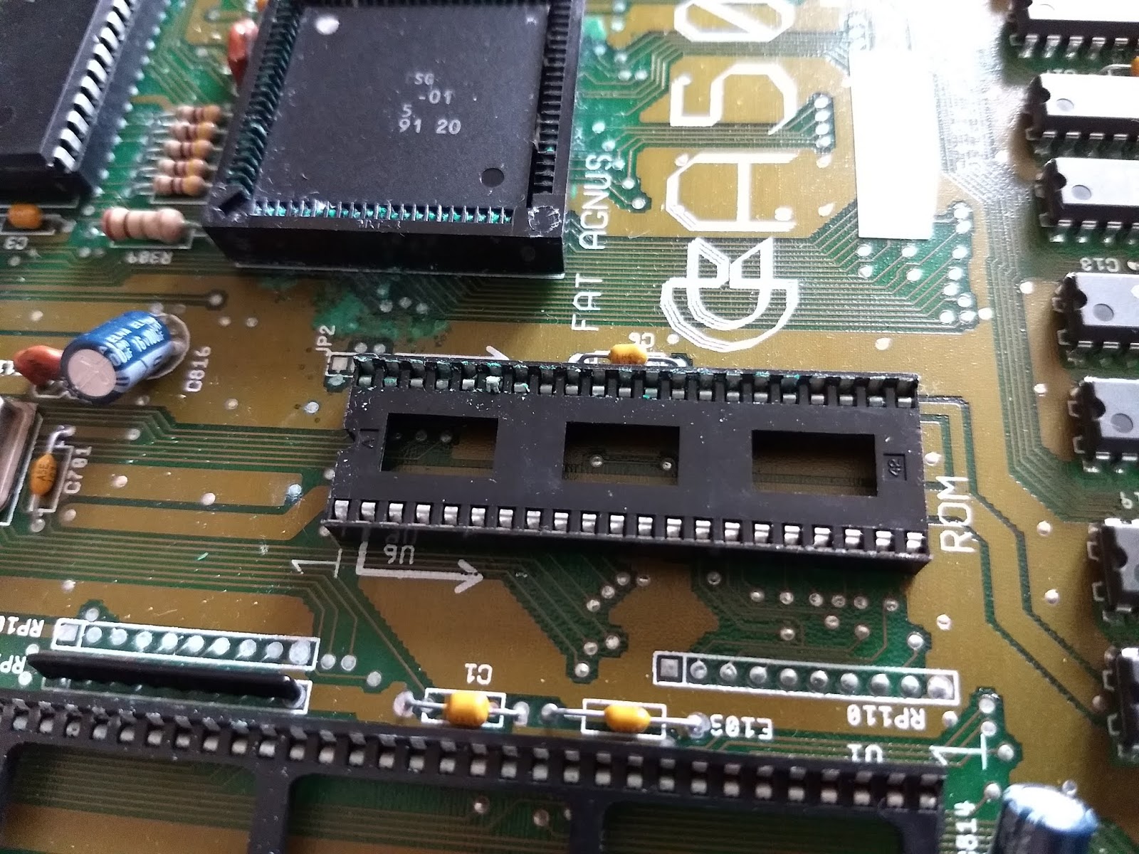
But, oh boy, that socket really is destroyed. I've not seen one with ALL of the pins corroded. Time to get the socket dispersion apparatus (a pair of cutters) on to it.
 |
| Socket nearly gone - damage marked with Sharpie |
I removed the ROM chip and CPU to keep them safe. The corrosion had also hit the ROM socket. I took some time to clean this up as I didn't have any other sockets. The damage to the contacts was largely superficial so I think I got away with it other than a couple of pins. More on those later.
 |
| Socket begone. |
With Agnus' socket removed I cleaned up the rest of the board. A dash of vinegar and then a gentle scrape with a screwdriver to remove the damaged solder mask, followed by a rub down with some IPA to get rid of anything left behind.
 |
| Clean and..err...bright. |
I had one Agnus socket left. I bought a pack of six originally. So that means that, over the last few years I've saved at least six A500s from a fate worse than recycling. Crikey.
Anyway. 84 pins later, Agnus has a new home.
 |
| Action shot! Agnus being replaced. |
 |
| Oooh! Fancy lighting... |
Now, that ROM socket. Two of the contacts actually broke off as I was cleaning it. The others were fine so I don't know what made these two susceptible to the battery acid but, cest la vie. To repair these I de-soldered just the single affected pins and pulled them out of the socket. Then I cleaned the holes out and, using a couple of new pins that had been pulled from a good socket I just pushed them back down into the socket and re-soldered the pin. It was a surprisingly simple and relatively easy fix. Unfortunately I didn't take any pictures with my camera but I hope my description gives a hint as to what I was doing. Note that this would probably only work on dual wipe sockets where the entire spring contact assembly can be removed relatively easily. Moving on.
First smoke test. Does it work?
No.
 |
| Green Screen. Not a surprise. |
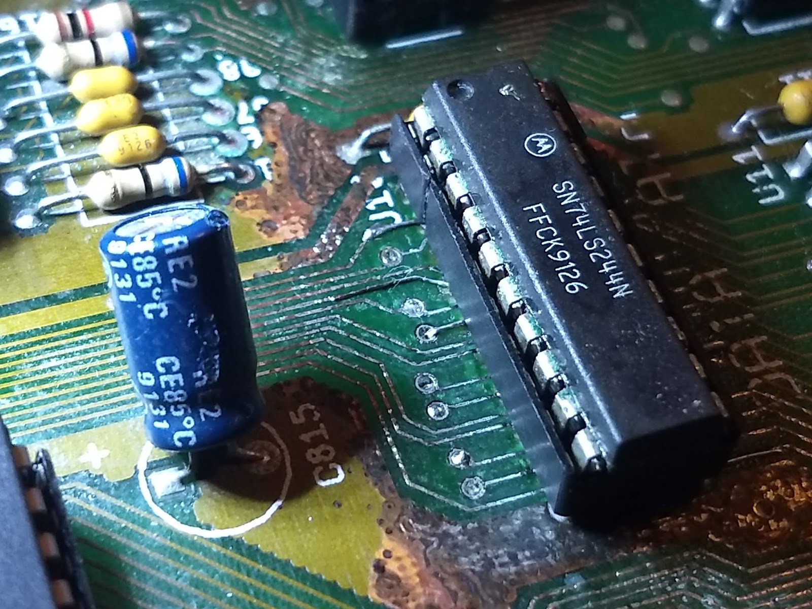
So, the next thing. Replace U10 and U12. These provide a data path for memory access and, as mentioned in many previous posts, this would be a very likely source of the green screen. The corrosion on these two chips was very bad, to the point where I didn't even bother trying to de-solder them, I just cut them off the board and cleaned up the areas affect. I had a couple of spares from a previous repair.
It did not look good...
 |
| Disappearing pads and traces... |
Out came the multimeter on continuity mode. Check. Beep. Check. Beep. Check. No beep. Note it down. Beep. Check. Beep. Check. No beep. Note it down. And so on for many, many traces. I ended up with a list of about nine missing traces.
To get the chips back on the board I installed sockets. The problem with this was that, as should be obvious from the picture above, there were several pads missing. To solve this I used fine single core wire and hooked a small piece down through each affected hole. Then I soldered it to the existing trace on one side of the board before gently pulling it tight and soldering it to the trace on the other side. Then, when a socket was inserted the leg had something to solder to. It worked quite well but was very, very fiddly..
 |
| Two repairs on this side. |
 |
| Three repairs on this side. |
 |
| And a close up.. |
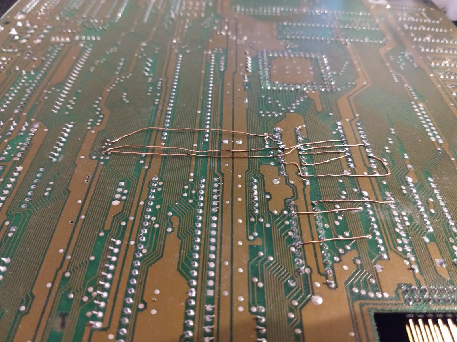
So now I was confident that the replacement chips in their sockets would work but there was still a long list of broken traces to deal with. This time I used coated copper wire which I think came from an old electronics kit. It's pretty fine but stiff enough to shape if needed. Here's the first attempt.
 |
| Spaghetti repair. |
 |
| Are we there yet? |
With all those wires attached, I tried a second smoke test.
 |
| It's ALIVE! |
I wasn't happy with the wires underneath though so I carefully re-worked them, taking extra care not to dislodge any of the pad/socket repairs. This was the final result.
 |
| Much better. |
 |
| Memory test |
 |
| Picture test |
Another A500+ lives to see another day.
Fin.