The PX-8 is, by todays standards, a bit lacking in features. The screen is barely a few inches high and as it's LCD it's not much better than a modern calculator. There's no backlight either, so actually seeing anything on it requires maneuvering your head around as if you're dodging bullets a la Neo from The Matrix. But it is still awesome.
It has a fairly standard, for the time, 64Kb of RAM built in, some of which is allocated to a RAM disk. This obviously reduces the amount of memory available for use of the system and applications so it's a rather good thing that there also came a 128Kb RAM disk. This is quite an unusual thing in that it bolts to the underneath of the PX-8 and, like the PX-8 is battery backed-up i.e. it is (in theory) more like an SD card than a straight RAM expansion - but more on that later.
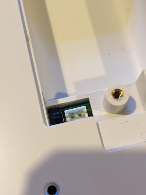
It came attached to the PX-8 and, sadly, when I switched it on I was faced with a sad little flashing cursor rather than the expected boot screen. First thing to check was the cable. This is very neatly tucked away behind a plastic panel on the back of the unit. A quick flick of the screwdriver revealed a rather short and stiff ribbon cable.
I removed the end from the PX-8 itself and tried to boot but no luck. So I tried to reset the unit by pressing the reset switch on the left side. Still no joy. Then I tried pressing the rest button while holding down the Shift and Num/Graph keys. And to my joy, the PX-8 sprang into life. Sadly though, this means that the RAM disk has issues.
First things first. We need to get it off the PX-8. This was much harder than I imagined and this should have been a warning sign that something was amiss. There are two large threaded 'collets' that hold the unit to back of the PX-8. I managed to undo the first with some difficulty but then the second just would NOT budge. I tried everything I had; a bit of IPA but no change, WD40 but no change, a gentle but nerve jarring tap or two with the handle of a hefty screwdriver. But nothing would move the fixing at all. Eventually, using a bit of brute strength I managed to twist the unit with the non-attached end swinging around and, after a tear inducing CRACK of plastic, it finally released itself. I had damaged one corner of the RAM Disk but it's not too bad and shouldn't be noticeable once it's re-assembled back onto the PX-8 (with fixings loosely attached!!).
Into the case I went and guess what I saw. A leaky battery. Oh. Shit.
 |
| Leaky battery - begone! |
At this point I took a slight diversion to also remove the batteries from the PX-8. It involved many screws and much cursing. If it had a screw head, it was undone...
 |
| PX-8 Leaky door - not good |
 |
| Damaged PX-8 battery connector |
 |
| Damaged PX-8 motherboard - Gah! |
A clean up was made of the PX-8 motherboard which resulted in 'SW3' falling off the board as it was badly damaged. I decided that this PX-8 will not have replacement batteries installed so I could safely bypass the switch so it was always set to "don't keep RAM contents".
Back to the RAM Disk. This particular device is quite clever as it is an 'active' RAM expansion. In a nutshell, it has its own Z80A CPU and associated logic to control the RAM and the interactions between the board and the PX-8. Very clever. The battery was there so that the RAM could be filled and then, with minimal power required, it could keep the RAM contents.
Given the age and the use that this board will now have, I again decided that no more batteries would be installed into the unit. No biggie but it does mean I'll probably have to 'format' it every time I switch it on. If that becomes an issue I may have to think again but for now, no batteries.
So, how do we find out what's wrong with this little beauty? I'd like to say I deliberated and came up with a carefully considered plan of simple steps to accurately and quickly diagnose the problem. I'd like to say that but really I've been 'scatter gunning' checks and tests at this a bit willy nilly. Here's a summary though:
RAM Chips
These are fairly standard 64Kb x 1 chips from NEC but they have an additional feature. Pin 1, which is not normally connected, has an extra function. These chips can keep their contents using an extra built in refresh function that uses about 50uA per chip. Nice. This obviously requires that a battery is in the unit but in my case, there ain't gonna be no battery.
Given that they're standard apart from Pin 1 it was time to break out the RAM checker. I've mentioned this in a previous post so I won't dwell on it too much here. I will add that I put sockets on the board for the non-socketed bank of RAM chips (2 banks of 64kb). I assume that one bank was socketed to allow the board to be used as either the 64kb or 128kb variant.
 |
| Heath Robinson RAM Tester |
Anway, 2 RAM chips failed. Boo!
But did replacing the RAM chips cure the problem?
No.
Z80A Check
This one was easy. I took the Z80A out of the RAM Disk and shoved it into a ZX Spectrum. It booted fine and ran the SmartCard V2 test ROM with no problems. I even booted up a quick game just to be sure. It's not the Z80A.
 |
| The trusty Z80A. |
Trace Checks
I have been bitten before by a damaged trace that caused nearly two weeks of confusion. It was an Amiga A500 motherboard and, as it happened, one of the data bus traces was broken. I did not intend to repeat that here, so a few hours of trace checking was carried out. Even though some damage had been caused by the leaky battery it seemed to be limited to the solder mask and all the traces are actually OK.
Still no cure then.
Signal Checks
This time I had access to a more substantial oscilloscope and I put it to use looking at how signals were being handled on the board. For the most part, the signals I found were sensible and a reasonable shape. That was until I reached the TC40H245 chip. Nice crisp signals were going in one side but were coming out very odd shapes the other. Could this be the issue?
 |
| Was it the 245, with the dodgy signal, in the library? (No.) |
 |
| Not sure this looks right... |
Fortunately, I had a couple of these exact chips floating around so after a quick desoldering and socket installation I swapped over to another chip.
Annnnnd..... no difference. It's still broken. :(
Chip Tests
So, other than the Z80A there is an EEPROM and gate array on this board. I can't really do much to check either (although I could dump the contents of the EEPROM - another day perhaps) but what I can do is check the other logic chips. I had to get them all off the board but thanks to my desolder station this was not a big problem.
I ended up with a pile of chips and needed to work out how to test them. Time to get organised!
 |
| Ooooh! Get you! |
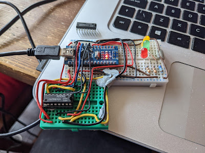
The plan was to wire up each chip and test the various gates and other functions while they were out of circuit. This is where I hit a major snag (and exposed a gap in my knowledge). I wired up a 4069U which is a 'Hex Inverter' so there are six inputs and six outputs, plus a ground and +v pin. Whatever the input is, the corresponding output pin is inverted. So if an input is high ('1') the output will be low ('0'). Or at least, that's the theory.
When I wired it all up with an LED to indicate the state of the outputs I found I could turn the LED on or off by moving my hands around the chip or by touching the wires. This was completely unexpected and I had to appeal to the Twitterati as to what the heck I was doing wrong.
In a nutshell, GROUND YOUR INPUTS. I had only connected to one of the gates on the 4069U which left the other input pins floating, causing all sorts of weird and wonderful effects. As soon as I linked all the inputs to ground, the problems went away and I could get on with the testing.
So from the list, 3C and 13C were fine. But 14C had a problem. This is a TC40H000P which is a quad 2-input NAND gate. This means that there are two inputs per gate and the output is '1' unless both inputs were also '1' in which case the output would be '0'. For two of the four gates the output was '1' no matter what the inputs were. I also noticed a strange 'hot' smell. After utilising my integrated digital temperature scalar unit (my finger) I found that the chip was freakin' hot and clearly up the swanny. Excellent. Or not.
 |
| Feeling hot, hot, hot! |
13C was the sister chip to 14C and behaved as expected. So did 6C, 4B, 6B and 7C which were also simple logic gates. Nice.
Then came the TC40H074Ps at positions 4C, 12C, 15C and 16C. These are dual 'D' type flip flops and I had to try and work out how to test them. I have worked with flip flops in the dim and distant past but they are but a distant memory.
Eventually I came up with this:
 |
| Flip-flop test circuit |
So, I put PRE and CLR to high and just left them there, then set 'D' to the input and attached an LED to Q as the output. Every time I toggled '>' (the 'clock' signal') then the setting on 'D' would be copied to the output Q. If '>' was low then no matter how many times I toggled 'D' nothing would happen and Q would remain the same.
For each of the four dual flip-flop chips I wired them up as above and then did the following:
- Attach 'D' to 5v
- Toggle '>'
- Whatever 'D' was should be on Q so with 'D' at 5v (i.e. high) then the LED should light
- Attach 'D' to GND
- Toggle '>'
- LED should go 'off' as 'D' is at 0v (i.e. low)
Not the most comprehensive of tests but it shows that the basics of the flip-flops are working.
So another four chips tested OK. We are at this point:
 |
| Progress! |
New 74HC00 chips to replace 14C have arrived and new 14 pin sockets are on the way, so the plan is to install new sockets, the replacement for 14C and see if it that makes any difference.
Stay tuned for an exciting* update soon!
(*this may be stretching the definition of exciting beyond reasonable expectations.)