Wednesday, December 20, 2023

Slow and Steady... Torch Triplex - Part 4

At the end of Part 3 of this series, my ATX power supply died. It's confirmed dead. It has gone to meet its maker etc etc. Fortunately, there is a steady supply of reliable and safe second hand ATX power supplies in the form of everyone's favourite auction site.

Not really. Most used power supplies are potential hazards and should be treated with caution.

The second hand unit I acquired was particularly interesting to me as it has -5v in amongst the various voltages on its connector. This is a voltage that doesn't appear on modern PSUs but it is required for the Torch. I also checked the inside of the unit before I plugged it in - I'm not stupid.

Bulging caps

Well, that's not good.

Way off spec - new caps required!
(No sh**, Sherlock.)

A few caps needed replacement but nothing too major and I soon had a working supply to get back to working on the Torch. Yay!

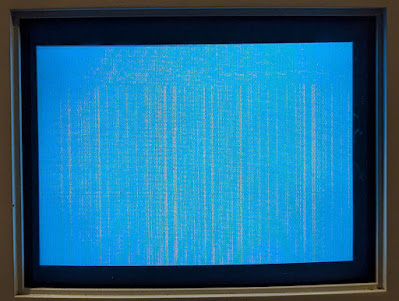
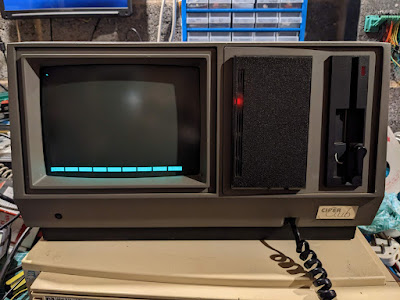
After wiring up the connector the Torch sprang back into life but, for some reason (still unknown), the garbage on screen no longer appeared. Instead, I noticed after about 15 seconds a forlorn sequence of beeps started to emanate from the monitor. Curious.

Well, not really that curious since the beeps are part of the startup error checking performed by the Torch in a similar way to the PCs 'POST' (Power On Self Test) beep codes. It was quite tricky to work out the sequence but after listening for a couple of minutes it seemed to be short-long-long-long. A quick check of the Caretaker manual revealed that this means the main CPU had 'timed out' i.e. it wasn't running. 

Now the CPU in this is a 68010 and it is directly pin compatible with the 68000 as used in the Amiga. And what do I have lying around? An A500 motherboard. Unfortunately, when I took the 68010 out of the Torch main board there seemed to be a leg missing (presumed gone). It looked like it had been melted.. Oh. Poop. After a quick repair I decided to continue with my plan to try it in the A500.


The melted leg.
(Poor quality as it's a picture of the screen of my half
working microscope..)

Legs eleven! (64 actually.)

One quick swap later and I was able to prove that the CPU itself is working fine as the A500 started up and booted to the familiar Kickstart 2.04 purple screen - well, grayscale actually as I got lazy and used the composite output on the board. It also ran the Amiga Test Kit without any problems.


68010 in an A500.


It booted. Yay!

I also checked the HLT and RST lines on the CPU (and MMU and DMA controllers) and they behaved as expected on start-up i.e. held low for a second before going high.


CPU, MMU and DMA controller

It was time to break out the oscilloscope. The Torch board has two distinct buses. One is primarily for the support processor and is called the QBUS and the other is the more standard address/data bus for the 68010 and supporting chips. This is called the PBUS.

Looking over the PBUS it was obvious that the bus is basically dead. There is NO activity at all. I am very puzzled by this. What could be causing a completely dead PBUS? All of the clocks are present and correct, power is present, although the 5v line is a little low at 4.45 volts. Perhaps there is a faulty device somewhere on the bus that is causing the failure...

There is some positive news. Thanks to some help and advice from a most excellent chap on the VCF forums I now know that the garbage shown previously when I booted up was actually the EPROM loading data into the video RAM prior to the execution of code. This is normally hidden as all the colours are set to pale blue but, for some reason, my Torch had a minor issue with the colour palette. Why it now works I don't know - which I don't like but will have to put up with for now.


Garbage seen previously - not now though. Hmm..


As a side-quest I got hold of a 16k*4bit DRAM tester to make sure that the VRAM is actually ok. All eight chips test as fully working so there's no problem there.


Compact and bijou. 4-bit DRAM tester

What is supposed to happen when the machine is switched on is that the Caretaker ROM, with assistance from the service processor, loads a piece of start-up code into video memory which is then executed by the main CPU. This means that my Torch is starting correctly but, because of the apparent PBUS issues, it's failing to execute the code and get the machine fully up and running.

The problem here is that there are so many components around the PBUS. There loads of driver ICs (LS244s and LS245s) as well as various latches (LS373s) and more. And that's not even including the 68010 CPU, 68450 DMA controller or 68451 MMU. At least I know that the 68010 is OK as I've tested this in the Amiga A500 motherboard and it works fine. I've managed to order a 68450 DMA controller for not too much from eBay so I should be able to confirm if that works and it's worth having a spare if the original is OK. 

The real fly in the ointment here is the MMU. When you search on eBay and the only result for a 68451 is a VTG daughter board from a VME/10 located in the US for around £660, you know that the MMU is going to be the purest of unobtainium. 

Gah.


Sunday, October 22, 2023

A mug's eyeful.

There used to be a reason for vintage computer collectors to head to car boot sales. Tons of stuff going for pennies used to adorn the tables of the happy 'booters' (well, maybe not adorn but there used to be a fair bit). An Amiga A500+ for £3, a CD32 controller for a fiver, Commodore 64 (boxed) for a tenner etc etc.

Those days are long gone. Anyone who has anything remotely vintage either sticks it on eBay or heads to the car boots with ridiculous prices in mind. Things are so bad now that there are even Facebook groups dedicated to the delusional people of eBay and the whacky and bizarre prices that they think their stuff is worth. My favourite was a chap in Scotland who for several months put his boxed Amiga A500 on eBay for the sum of £1000 starting bid. If that had been serial number 1, signed by Jeff Porter and hand delivered by R J Mical, it might have been worth it. In reality, they're worth less than 1/10th that.

I digress. 

A few weeks ago, Crashed Jr(1) let me know of a 'PC' that was at a local fete for a very reasonable price. He sent me a picture and it turned out to be an Amstrad PCW9512. 


I know this! It's a CP/M system..

For those of you not in the UK, the Amstrad PCW9512 was one of a range of low cost PC like machines that dominated the early low-end small business computer market. I actually used one of these many, many years ago at an estate agents I worked at. It uses CP/M and has a primitive word processor and, originally, came with a printer too - no printer with this one but that's fine.

So, does it work? Well, the thing with these machines is that they are very much built to a price point so to actually get this thing up and running requires either the word processor disk or the CP/M disk. Switching on with no disk in the drive gives a beep and a white screen and nothing else. Without the disks, this is a lighter than you'd imagine paperweight.

And on the subject of disks... The more astute of you might have spotted that this thing actually uses 3 inch floppy disks rather than the more usual 3.5 inch disks. The story is that Alan Sugar managed to blag a boatload of 3 inch drives dirt cheap and so they went into every machine Amstrad generated that used floppies (CPC6128, PCW8256 etc etc). Not sure if there's any truth to that but anything's possible

Anyway, this unit did exactly as expected when I got it home, i.e. it has no disks so it just shows a white screen. I did have a 3inch disk for a PCW8256 but I didn't realise at the time they aren't compatible so when I put it in, nothing happened. But not exactly because of the incompatibility..

The floppy units in these machines use a drive belt to turn the spindle motor that makes the disk spin. And we all know what happens to rubber belts as they age. They turn into a thick, black goo that is horrible to remove from everything. To check the state of the belt I had to take the back of the machine off, then dismantle the base from the CRT so I could get the drive unit out. After taking the back off I realised I wasn't the first person to do this.. 

There are two controls on the side of the unit to control the brightness and contrast. The contrast knob had been hot glued. Oh dear. So as I took the case off, both of the potentiometers for the controls basically fell apart. Dangnabit. I managed to collect the bits and then desolder the bar that they were both attached to. 


Broken. Darnit.

After a bit of head scratching I realised that all that had happened was that the protruding control knobs were held on by plastic stakes that were melted to hold the front cover plates on. By gluing the plates back on - and trying to avoid sticking the knobs too - I could probably get away with re-installed these original ones. So that's what I did. I gave the knobs a twist to make sure they didn't stick and then let the glue overnight to cure. And the knobs were stuck solid the next day. Solved that by a firm twist with a pair of pliers. 

Fixed! Yay! Don't play with the knobs
or they may drop off.


Back to the floppy drive. The belt had, as predicted, become a sad strip of goo and needed to be replaced.


Belt has started to disintegrate

Gooey belt stuck to the main flywheel. Yuk!

In the course of moving the little green circuit board I heard a slight 'plink' of something hitting the floor. Unbeknown to me, these drives, also clearly built to a price point, have a small metal pin which drives the write protect function. This pin is not secured and simply drops into a tiny hole in the drive body. And simply drops out if you're not watching carefully..onto a small piece of patterned carpet...with the debris of many hours of soldering and other vintage computer restoration activities. 

Bugger.

Of course, at the time I didn't realise this was the case. But somewhere in the depths of my slightly confused middle-aged brain an Emergency Action Message was triggered that told me I should check the floor for something that I had never laid eyes on before. And sure enough, after half an hour of crawling around in the dust, solder blobs and occasional annoyed spider, I found it.


Dropped pin. Gah!

After checking the circuit board I located the write protect switch and made sure the pin was dropped into the correct hole. 

Back to the drive belt. After cleaning away the remains of the sticky old belt, which involved lots of scraping and cleaning with isopropyl alcohol, fitting the new belt was simple. The PCB was screwed back into place, which also then secures the write protect pin (grrr) and everything was ready to be re-assembled.


New drive belt goodness.

Controls re-installed

With the unit back together all I need now is a disk with the correct software on. I have a disk image for CP/M for PCW9512 but there are a couple of problems.

I have an additional floppy drive which is 3 inch but when I plug it into power, the drive makes 'chunk chunk' noises and the power supply (courtesy of the Cifer) goes into meltdown. A closer inspection shows that there are leaky caps just at the power connector.

Ohhh, another 3 inch drive.


It's an EME-01 (apparently)


Track damage just above the orange 
wire (mid left)

More track damage under the brown wire

Although I didn't have a full set of capacitors I did have the two values next to the power socket and a couple more on the main board. And changing them solved the problem. Bizarrely, that's the second time that changing the caps has fixed a fault and both times it was a floppy drive.

This 3 inch floppy drive is fully compatible with the Shugart standard. This means that I can use the awesome Greaseweazle with it. I managed to get a record of the disk that actually came with this drive - which was for the PCW8256 - using the Greaseweazle software with the intention of writing the the CP/M image for the PCW9512 back to that disk. 

But there are two major problems. This is only a single sided drive. The drive in the Amstrad is double sided. 

Second, the additional floppy drive only supports 40 tracks per inch whereas the PCW's drive is 80 tracks per inch. 

Arse.

Looks like I'll be heading to eBay for a CP/M disk then. Darnit.

It's worse than that, he's dead, Jim.. - Torch Triple X Part 3

Before anyone panics, the Torch isn't dead (I think). Rather, my ATX power supply is. While I was probing around the board, looking at signals, I noticed that the cyan display had actually turned magenta. This was different so I switched off the ATX supply, waited 20 seconds or so then switched it back on. 

And I got nothing.

After a little panic I realised that the green LED on the ATX supply hadn't lit up meaning that the supply was off. The red LED was lit though, indicating that it was in standby. Hmmm. I initially thought I'd popped a thermal fuse so I left it overnight and tried the next day.


Red standby LED is still lit
(centre bottom at the end of the black box)

Still dead.

So I tried checking the internal fuse and that was OK too.

Bugger.

Now I am in the situation where I'm not sure if the power supply died of old age, or whether a fault was on the Torch board that killed it. And, if there was, has that fault damaged the Torch mainboard? I know it was drawing a lot of current but the ATX supply could provide a crazy amount i.e. 25 amps at 5v and 16 amps at 12v. I could try and drive the board from my bench supply but then I can only provide the 5v. I may have to bite the bullet and buy another ATX power supply. I did have a spare but it went into the Amiga A2000. 


Unlimited Power! (Well up to 280W..)


To keep myself amused and useful I decided I should look at the schematics of the Torch and try to re-create them in KiCAD. 

I have used several CAD packages in the past but KiCAD is specifically aimed at preparing electronic PCB layouts and schematics. The learning curve is not too hard if you're only copying a schematic - and when I say copying I mean "make it look like the picture, I don't care if I've had to modify a 68000 block diagram to make the MMU..." so there's no chance of using my output to generate a new gerber file for the motherboard or anything daft like that.

The main reason I'm actually quite keen to get the schematics done is that the originals that I have are not really originals. They're photocopies of hand-drawn (possibly) originals and so the quality in some places has really gone down and there are several areas, notably at the very top or bottom of the drawings, where some information has been lost. This isn't as drastic as it sounds as it can pretty much be derived by looking at the context of the lines that seem to stop suddenly at the top (or bottom) of the page.

Anyway, here's an example which shows the 'Bus Masters' and is probably one of the most complicated of the drawings to generate.


Bus Masters. This is one of the most complicated ones.


While I work my way through the schematics and try not to lose my sanity, I will start searching eBay for an ATX power supply that also has -5V. 

“If it were easy, everybody would do it. Hard is what makes it great.”

Monday, October 02, 2023

With Great Power... - Torch Triple X Part 2

Quick re-cap. The Torch Triple X is uber rare, and has a slightly whacky power supply which allowed for 'soft start' and 'soft shutdown'. Unfortunately, to achieve this, amongst other things, the power supply actually had a battery in it.

Curse you generic battery supplier!

The leaky battery has very seriously damaged the PCB for the supply. In some spots the track has just gone completely and several resistors just disintegrated during cleaning of the board. So I replaced the resistors and the RIFA cap. I also bridged the broken tracks and reflowed as many joints as I could. Battery leakage is a real pain as, apart from the destruction of tracks it also combines with solder to give a grey, hard crystalline lump that is almost impossible to solder. This can be corrosive and loses conductivity so it is worth trying to sort out.

After several hours of work, I was ready for the first switch on. Following advice from Twitter (now 'X') I took an incandescent bulb - actually an old spotlight with screw cap - and soldered a couple of wires to it so that I could add it in series with the live wire. The idea is that if there is a fault, then excess current flows through the bulb making it glow bright. A dim bulb means that there isn't excess current - but no guarantee that there's no fault...


Good job I still had those bulbs...


So, what should happen is that when I switch the power on, there should be nothing from the supply until a pair of pogo pins have a small capacitance - provided by a finger - applied across them. This signals the board to start up and provide 5V to the main board, whereupon the main board will then send a 5V signal back into the supply to signal it should stay on.

For my test, I'm just intending to poke the pogo pins, check the supply starts up and then wait until it shuts itself down after two seconds (it does this automatically if the 5V from the main board isn't seen after two seconds). Here's a quick video of the first switch on:


Yikes.

So, unsurprisingly, I decide against poking the pogo pins with my finger.. I tried switching on again a few times with similar results. It doesn't get any better in slow motion..


Something is very wrong with this supply and, despite my best efforts, it may be beyond my skill to repair. The bulb going bright and then dim is fine as this is likely the capacitors charging. However, the loud cracks and arcing from the relay and the extra arcing from somewhere else on the board are not fine.


Ohhh - extra unexpected arcing. Spicy!


But fear not. After some careful thinking I came to the conclusion that the 'soft touch' feature could probably be bypassed if I used a straight PC ATX power supply and fed it straight into the motherboard. So I removed the connectors from the original supply and soldered some wires to the back of them allowing me to use my Heath-Robinson bench ATX supply. 


What could go wrong?


Going for broke and putting it all together..


So, it came to the first switch on. And I got nothing. And I mean, NOTHING. Hmmm.

After poking around the main board for a while I came to the conclusion that there must be a short to ground on the 5v rail. My reasoning was that the 5v was showing 0.3v. The resistance between ground and 5v was about 12 ohms (foreshadowing).

And now, dear reader, I made an error. One that may haunt me but I hope not. I decided to inject some voltage into the board using my bench power supply to check if there was indeed a short. I started at 4.8v with a current of 100mA. The voltage immediately sagged to virtually nothing and the current limit kicked in. So I increased the current to 500mA. Same thing - and I also realised that nothing on the board was getting hot or even warm. Increase to 1A. Same. 2A and I got the same. At this point I stopped as the current was going somewhere but I could not work out where.

Back to basics, I had another look at the connectors. But this time I took the time to take out all of the conductors from the plugs (relatively simple to do - poke the retaining hook with a sharp pointy thing and gently pull them out). And they were not good.

So I spent about an hour carefully dipping the conductors in white vinegar. The immediate 'fizz' made me realise that they were still heavily contaminated with battery guts.


Removing conductors - sharp pointy thing
in hand.


Then I took some very fine sandpaper and gently brushed the inner part of the female conductors and the outer part of the male conductors for extra cleaning. Putting them all back together I tried again, but this time with just the board and the 10inch monitor connected.

And this was the result:

It's alive! Somewhat..


This is a great start as it shows that there is still some life in there. As a separate exercise I also tried the clean cables on the floppy drive and hard disk 'ring'. Both sprang into life immediately where previously they had appeared to be dead. Most importantly, the hard disk started with no real complaints and made all the right noises for an old but very much working hard disk.

So the blue screen confirms that the video output circuitry is working. But how do we get any further?

After reading the technical manual, which is crap by the way, I realised that the old power supply would hold the NMI signal on the 6303 processor low for two seconds to start up. Grounding the correct pin on the main board connector would achieve the same thing. If the computer is switched on and at the blue screen then holding the NMI to ground for a couple of seconds will generally switch it off i.e. the display goes blank. 

This is also positive as it shows that the 6303 processor is doing its job and sending the right signals out to shutdown the system. 

After a couple of hours of probing and fiddling I noticed that after a certain amount of time the display would change. It would show a definite rectangle of garbage at the top followed by lines running down the screen. Sometimes these would start out black and then change to a dark yellow. I tried to take a photo and quickly realised how difficult it is to take a decent picture of a CRT! The 'best' pics are below:

Garbage.

More garbage.


From this display I am going to take a punt and say that there could be a RAM problem here. What the system should do when it starts up is copy the 'Caretaker' program to RAM and run it. This is what checks to make sure it knows you have the 'key' disk and then starts loading up from the hard disk (if present). I'm speculating that there is an issue with the RAM that is preventing this from happening or there is an issue with the video RAM that means I can't see what's happening. The video RAM on this is an odd chip I've not seen before and that is not supported by my RAM tester either - HM48416 which are 16384 word x 4 bit chips i.e. they have 4 data bits per chip. 

Another quick meander through the documentation showed that the system should beep to indicate startup and also provide patterns of beeps to identify issues which would be really helpful at this point. But this machine has been silent. I think that this is because the power supply does not have -5v. I had assumed that this was for the serial ports only but it looks like it may also be used in driving the sound signals that get piped through the monitor. Or should I say that there are + and - connections labelled 'speaker' in the video connector so that may be an assumption on my part.

To get -5v I could modify the -12v output from this power supply. I first tried a straight voltage divider but this didn't seem to work and I ended up with +0.3v on the -5v rail.. I may have to look for an LM337 or LM137 negative regulator.

But my money is on it being RAM in any case. More soon.


Monday, September 18, 2023

Anybody? No? Disk. Anybody? No? Disk. Anybody? No? Disk.

10 out of 10 if you get that reference..

With the appearance of two rare machines in my garage i.e. the Cifer and (gasp) the Torch Triple X, I started to think about the media that came with them and what, if anything, I could do to preserve the software on them. 

Torch Triple X - Rare

Cifer 1887 - Also, a bit rare

Although I am a kid from the 70's I never owned a computer with a 5 1/4 inch floppy disk drive. I jumped from the ZX Spectrum+ to a SAM Coupe and then to an Amiga A500+. The Speccy used tapes and any floppy drives available for the speccy were way outside my 10 year old budget, costing more than the computer itself. Then the SAM used tapes or a 3.5 inch floppy drive and the Amiga also used the more modern 3.5 inch disks. So I had very little exposure to the delights of the greatest actual 'floppy' disk format.

Until now...

From having no 5 1/4 inch disks just over a year ago I now have boxes and boxes of them. A few are software for the Psion organisers, a big bunch are for the Cifer and the rest now for the Torch Triple X. All of these disks need to be preserved in some way, some more than others - for example the Torch has a 'key' disk that MUST be inserted the first time the machine is switched on or else it's just a large white box that does not very much. 

The first problem is that I don't have a PC with a 5 1/4 inch drive in it. I don't even have a working desktop PC that would accept one having long since succumbed to the portability of a laptop (even though my old HP is massive and weighs as much as a small child). The only physical drives I have are the twin drives in the Epson TF-15 unit, the drive in the Cifer and now the drive in the Torch. 

After some investigation I realised that I don't need a desktop PC to connect a drive to now that there is such a thing as a 'Greaseweazle'. This most excellent device with software by the ever awesome Keir Fraser is a small board that has a standard 34-pin connector and is powered by USB. More importantly it allows the contents of a disk to be captured regardless of its format (although common machine specific formats are supported natively too). This is achieved by the unit capturing a stream that comprises the variations in the magnetic flux on the disk surface itself. This can be saved into either RAW or SCP format for (in theory) writing to a new disk. Other formats can be written too.

It's worth noting that a floppy disk is basically a piece of plastic cut into a circle and coated in iron oxide that is somewhat the same as used in cassette tapes. Data is stored on the disk by magnetising small parts of the iron oxide in specific patterns. To read the disk back a read head simply converts the magnetic flux variations into electrical signals that are converted back into data. The Greaseweasle records this flux and puts it into a file for later use.

So the Greaseweazle I have is a V4 unit supplied by the excellent chaps at RetroPassion. The unit itself has a 34 pin connector, a four pin power connector and a USB type 'B' connector. There are also some jumpers that can be set, the most useful of which inhibits the units ability to write to a disk, providing some protection against idiots (who d'ya mean?) who might accidentally overwrite vitally important data...


It's not greasy and it's not a weasle...

I quickly 3D printed a case for it (find it here) and then set off to find a floppy drive. Because the unit uses a standard 34 pin connector this means that, in theory, any standard floppy drive will work including 3.5 inch drives, some 3 inch drives (may need an adaptor or the drives internal 5v disconnecting) and most 5 1/4 inch drives too. The first drive I found was a Chinon 'tall' 3.5 inch drive from an Amiga A500. 

After connecting it up I was disappointed to find that the drive did nothing, even with the power connected. After a quick search I found that some 3.5 drives use 12V which the GW cannot provide, requiring a separate power supply. The Chinon is one of them. Another quick scrabble in the garage produced a black PC unit that I had forgotten about. 

I wasn't sure what state this was in but I connected everything up and stuck in an Amiga disk - this is supposed to allow copying of disks agnostic of the system after all. :)

Mitsumi PC drive

Next question was what format to use. There are two main 'stream' formats. These are SCP and RAW. If using RAW you need to make sure you direct the output files to a folder and give them an appropriate name. The SCP format writes a single file so that's what I went for.

Initial results were disappointing. Using the HxC floppy emulator analysis tool the top layer was covered in orange and red and just didn't look right. After stripping the case off the drive I cleaned the heads and also realised that there was an adjustment slot on the spring holding the top head down. I moved it up to the highest setting and tried again.


Drive adjustment in progress...


Success! The stream created showed (almost) all green on the analysis tool in the excellent HxC floppy emulator software.


Then, using the HxC software, I converted the SCP stream into an Amiga ADF and successfully mounted it in WinUAE. Nice.

After this success it was time to move on to the 5 1/4 inch disks. As I had the Torch in pieces to try and repair the power supply I nabbed the floppy drive from that. Fortunately, the cable with this unit had the correct 34 pin connector for the Greaseweazle end. As I have a different laptop in the garage - a much smaller and slower HP that runs Linux I had to install the Greaseweazle software again as well as the HxC floppy emulator. Not quite as straightforward as the Windows installation but it all worked in the end.

First attempt at connecting everything up and the GW reported that it couldn't find an index. This normally means that it is looking for the wrong drive number. I changed the '--drive=' value in the command line to '1' from '0' and tried again but no luck. So I tried '2' and then jumped a mile as the drive clicked into life.


After reading in a disk image from a CPM system disk for the Cifer I was disappointed to see that the disk analyser showed large patches of red and orange as if the disk wasn't formatted or had errors. This was slightly disturbing but I persevered and tried to write the image to a blank disk and then analyse the pattern on the newly written disk. It did not go well.

CPM disk for the Cifer read using the Torch floppy
Something ain't right..


The scp stream written to a blank floppy and read back in
Definitely not right..


Hmmm. I started to think that this must be the drive at fault so, after some deliberation and a lot of moving stuff around I took the drive out of the Cifer and tried again. This time the results were startlingly better. Every track was green, dark green for data and light green for formatted but empty with only a couple of orange/red spots. Awesome!

That's more like it...


So, what is wrong with the Torch drive? I'll give you one guess. 

Yep.

Capacitors.

There are a few electrolytic caps on the control board of this drive and some of them have leaked. A video here from the most excellent Mike, showed that his drive of the same model was doing exactly the same as mine before being re-capped i.e. with a clicky bouncy arm thing. And, for the second time, replacing the caps fixed the issue (or to be honest, a partial re-cap as I didn't have all the values but it was enough.)

Torch floppy drive after (partial) recap

So, now can this drive read disk streams as well as the Cifer drive? 

It works!


Oh yes.

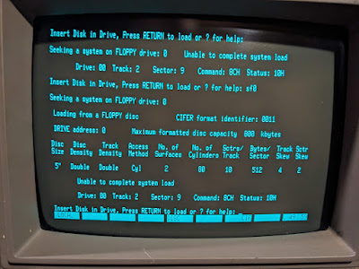
So, now I can capture disk images, regardless of format, can I write them to a blank disk and get them to work in the Cifer? Well, sort of. For some reason, just copying the scp stream back on to a disk always gives an error when the Cifer tries to boot.


Track 2, sector 9 every time... very odd.


Looking at the flux representation showed a strange fuzziness on the written disk compared to the original and I still don't know why. More bizarrely, this fuzziness appears if I use the Cifer drive to do the reading/writing too. 

Left box shows original, right box shows written disk with 'wiggle'


This could be down to my only being able to do a partial re-cap on the drive resulting in a reduced bouncy arm thing for reading (it's a 'head load' arm to be precise) but still slightly bouncy for writing. I will see about ordering the rest of the caps.

For now, I worked out that I could go via an intermediate format, in this case .IMD which is a format associated with a PC utility called 'Image Disk'. This is apparently a very useful and powerful tool but it requires a PC with 5 1/4 drives etc which I don't have. But the HxC software does write this format, as does the greaseweazle tools I think. In any case, after writing an IMD file of the CPM disk to a blank floppy I stuck it in the Cifer and booted it. 

And it worked! Yay!

Cifer booting! YES!

So, just one last thing. That 'Key' disk for the Torch. Can I read that too? You betcha!

Torch Key Disk Image - backed up and saved. Phew!


Back to the Torch next time.


Monday, September 11, 2023

A Torch - well every adventure game needs one of those, doesn't it? - Torch Triple X Part 1

Not that sort of torch. This is a Torch computer. Specifically a Torch Triple X (I say!). Released in 1986 this was a UNIX workstation based on a 68010 CPU with floppy disk, hard disk, UNIX SysV and a colour GUI with a mouse. This might seem rather advanced for 1986 but, to be fair, the Amiga was a contemporary being released in July 1985 and that had a similar, if rather more orange and blue, OS and a rather uncomfortable mouse.


It's a Torch. With two monitors.
Nice.


This particular Torch Triple XXX (which I shall refer to as the T3X to save my middle aged typing fingers) was once used as part of a command and control system and was last switched on sometime in the 1990s. As a project, this is going to be a rather long term thing. There are several slightly odd things about this machine that have to be sorted before any electrons from the mains supply go near it. 


Under the hood. Floppy to the left, winchester in the middle
and power supply on the right.


Under the hood 2 - The main board but note the 'Limpet 
Board' on the right giving an extra 1mb of RAM

First up, the power supply. It has a battery. Which has leaked. It also is essential for the correct operation of the system as it uses an innovative (for the time) capacitive 'on/off' button that would rely on the capacitance of a finger to switch the machine on. If the machine was on and the button was pressed, it automatically shut the system down gracefully. Innovative? Maybe. A pain in the arse over 35 years later? Yes, yes it is, but I'm getting ahead of myself.

Second, the hard disk. It uses a small winchester disk and, if you're a regular reader, you'll know that I don't have a lot of luck with ancient hard disks. The Mac Classic II and the Cifer spring to mind.. Fortunately, I have a full set of SystemV floppy disks in a box. Which leads me nicely on to..

..The 'key disk'. This is a floppy disk that MUST be inserted when the system is factory reset. Without it, the unit is a nice heavy doorstop. When it's been inserted once, the battery in the power supply (remember that?) keeps the information stored so you don't need to use it again. Until the machine is reset. Or the battery dies. Or it goes into storage for twenty years before landing in my garage.

Let's take a proper look at the power supply first. It looks fairly standard but when I took it out it was obvious that some moisture of some sort had got in to it. At this point I hadn't realised that there was a battery, but this innocence was soon lost when I realised why the damage I was seeing looked startlingly familiar... 


Battery damage. :(

White barrel battery. I sentence you to be removed...


Quick aside. There's a freakin' huge RIFA in there with a dirty great crack down it. Magic smoke has already leaked out clearly.


Smokin'...


The battery damage is extensive on the bottom of the board. I scraped away the solder mask on the tracks that were affected. Then I carefully re-flowed all the joints that had become dull and grey. This wasn't straightforward as the battery chemicals react with the solder joints to create a grey, crystalline blob that doesn't really melt very well. I had to take my soldering iron and copious amounts of flux. Heating each joint I could see when the solder under the gunk started to melt and then used the solder sucker to get rid of the worst.


Repairs in progress.


Despite my best efforts, there are at least four pads that have disappeared or broken. One track has basically been eaten away to nothing and will need a chunky bodge wire to repair.


Track eaten away by battery leak.


On the other side, there were several component casualties too, although they were all resistors. Seven in total basically fell of the board due to the corrosion of their leads from the leaky battery. These should be easy to source and replace though. No other components seem to have been affected as badly. A simple scrape and clean up of the diodes, transistors and capacitor legs seems to have done the trick.


Casualties of (battery) war..


And that's about it for part one of this project. I need to order some new resistors (don't feel happy using the uber-cheap skinny bits I bought from a man who claimed to be in the UK but was clearly located somewhere in China) and, of course, a replacement for the RIFA smoke generator.

More soon..