On to more pressing matters. Does this board now work?
No. Black screen. Still. Bugger.
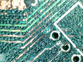
Right. After poking around a bit I removed U12 by carefully cutting it off the board. Then I decided to install a temporary socket made up of off-cuts of my Paula/Gary escapades. This would enable me to install a replacement chip to see if it was just a simple logic chip replacement required. While I was there I also noticed a bit of a problem...
 |
| Is this a broken track I see before me? |
 |
| Yes. |
A track had broken, most likely due to my cleaning efforts which, from the state of the board, looks to have dislodged a piece of the substrate which was probably damaged by the battery leak. This has left a small but significant 'pit' which obviously made it easy for me to catch the metal track as I continued cleaning. This is no big deal and I installed a temporary repair just while I carried on troubleshooting. This was a tiny sliver of wire, soldered across the two ends of the broken track to form a bridge. Unfortunately I forgot to take a photo but, as I am bound to say, it looked like new*.
*did not look like new.
Anyway. At this point I thought I should check all the tracks from Gary through to the logic section seeing as Gary took the brunt of the corrosion. All was OK except for one track. For some reason I could not get continuity from pin 2 of Gary to the 'north' side of R102. I thought that this might be due to corrosion on the solder joint of R102 so diverted off for a couple of hours to de-solder all of the resistors and capacitors in that area.
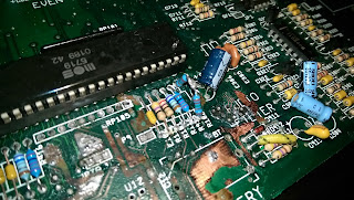
De-soldering this components was easy. Except when they disintegrated. Like R102. And R111. Oh, and R114. And, in fact, most of the resistors in the two little banks of components located below Gary on the motherboard.
I think the phrase rhymes with 'clucking bell'.
To cut a long story short, I scraped together most of the resistor values I needed and cobbled together a couple of bodges (resistors in series) to make the values I didn't have. New resistors are on their way but I haven't got them yet...
 |
| Temporary Resistor Repairs |
Then, once I'd finished faffing with resistors I turned my attention back to the non-continuity of the track from pin 2 of Gary. Even with the new soldering in place, there was still no joy so I resorted to a short jumper wire to get around the problem. It's fairly discrete and I suspect I will leave this one on the board as it is not visible when the board is installed and does the job quite nicely.
 |
| Jumper on Gary |
With all this done it was time to try and plug him in again.
Does he work? No. Green screen. BUT that is an improvement and shows we're getting there. Green screen is shown when there is a problem with the chip memory. It can be caused by a multitude of faults but the most common are a bad memory chip, bad logic chips or a broken Agnus.
I have ordered new logic chips (74LS244 and 74LS373) as they are the cheapest and simplest to replace and they should be here early next week; also included should be the resistors and some sockets for the logic chips. If they don't make any difference and I end up having to scrap the board at least I get to take back the new chips.
In the immortal words of The Carpenters, "Please, please, Mr Postman (Why's it takin' such a long time?)"...
No comments:
Post a Comment