Saturday, May 14, 2022

Pin. Pin. Pin. Pin.

Pinouts. Lots of pinouts. Or at least I thought I should properly document the pinouts of the UD-80. This will be the last post on this for a little while as I still have lots of other stuff to look at, including a TV with a faulty SCART input...

First up, SCART.

RGB Cable - 6-pin DIN to SCART

The socket is a 6 pin DIN (240 degrees) socket arranged in the following order:


UD80   Pin            Pin  SCART

GND    1: ---------- : 18  GND

CSYNC  2: ---------- : 20  SYNC (via 470R resistor & 10uf cap)

RED    3: ---------- : 15  RED

GREEN  4: ---------- : 11  GREEN

BLUE   5: ---------- : 7   BLUE

+5V    6: ---------- : 16  RGB BLANKING


Diagram below:

What a lovely diagram.

One key thing here is that I'm not convinced I've got the RGB in the right order. But I would point out that the PX-8 and UD-80 are monochrome, so what difference does it make? :) At least I'm fairly sure that GREEN is in the right place at least...

The CSYNC signal was measuring 5v which is TTL level and a bit over the top for the SCART standard. Sticking the resistor in there, when it's connected to the 75 ohm impedance TV connector, means the output is a much more standard 520mV (thanks to the video by Voultar where he describes the issues with old equipment - see here for that video). The capacitor de-couples any DC bias in the signal.

Here's one I made earlier:

GAAAH!!

And here's one where I put the SCART plug screw on before I re-soldered the plug back on:


Remembered this time...

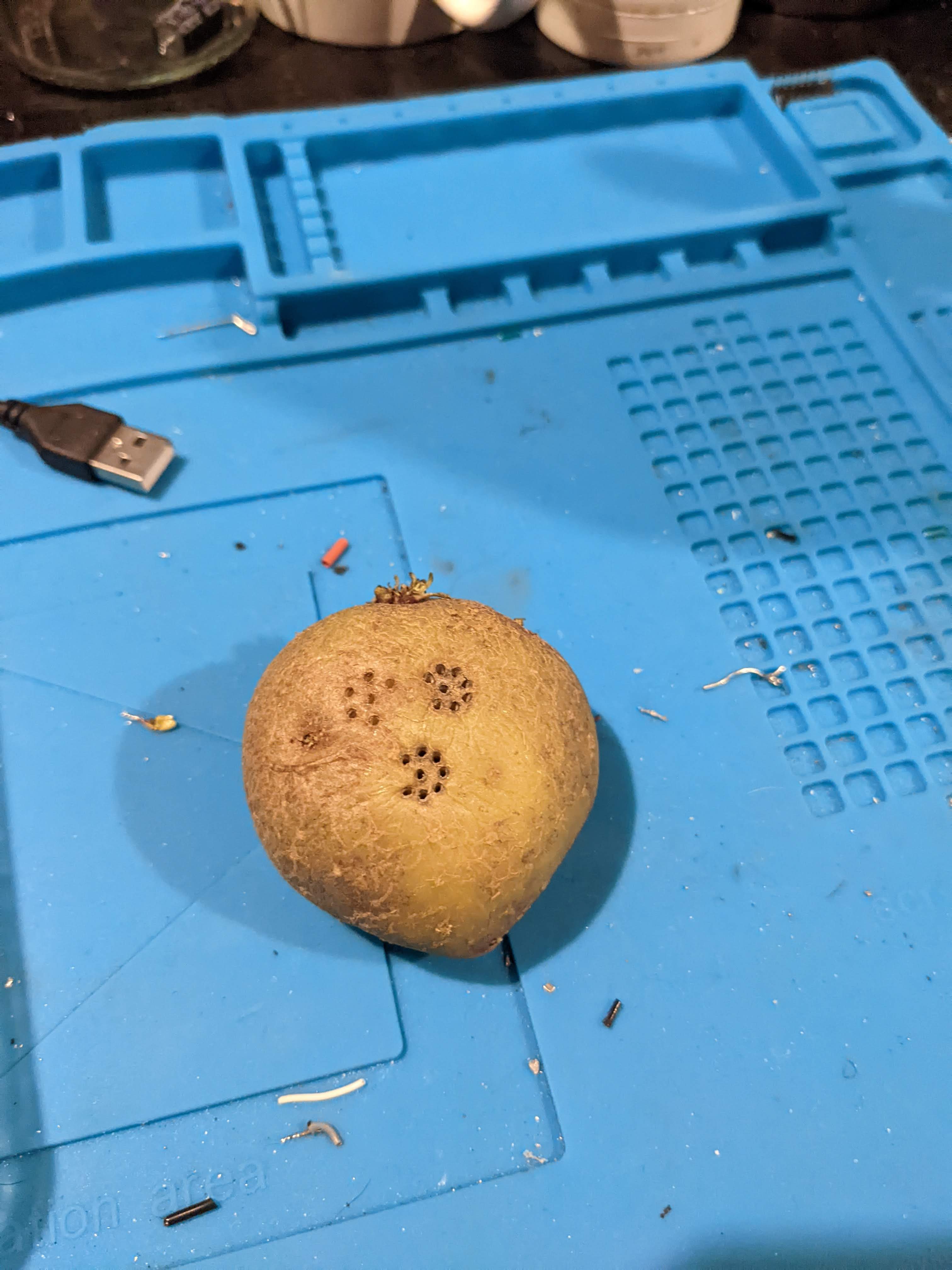
And, of course, I must not forget the patented DIN plug 'Maximum Assistance Super Hold' (MASH) device i.e. a potatoe:

Hmmmm. Potatoes....

One of the best things to hold the DIN plug so the pins stay in place and don't fall out while you're trying to solder the plug. An excellent tip there. As you can see I did the 8 pin and the 6 pin DIN plugs for the UD-80 with this particular MASH.

Does it work? Of course.

WordStar. You youngsters don't know you're
born. 

A whole 2k free on the A: drive!

Rather interestingly, there is some slight distortion towards the bottom of the screen that looked similar to the composite interference. I suspect this may be related to the UD-80 rather than any issue with my cable but I might investigate at some point.

Next up, the UD-80 connection itself.


UD-80 Serial Cable - 8-pin DIN to 8-pin Mini-DIN


The socket on the front of the UD-80 is an 8-pin 270 degree DIN socket. It can accommodate a 5-pin 180 degree plug since only pins 1 to 5 are actually used. The pins are arranged as follows:

    UD80  Pin            Pin  PX-8 RS232

  GROUND  2: ---------- : 1   GROUND

 DATA IN  1: ---------- : 2   DATA OUT

DATA OUT  3: ---------- : 3   DATA IN

     CTS  5: ---------- : 4   DTR

     DTR  4: ---------- : 5   CTS

     N/C  6:            : 6   N/C

     N/C  7:            : 7   N/C

     N/C  8:            : 8   N/C


The PX-8 can, apparently, use either the RS232 or Serial ports with the UD-80. Everything I have done so far has been with the RS232 port.


UD-80 Operation


The UD-80 replicates and extends the display of the PX-8 from an 8 line LCD display to an 80 or 40 column display with 24 lines via a composite or RGB output (see above for info on RGB). The UD-80 comes with a built-in extension for WordStar to allow the use of the additional screen real-estate. Other applications need to be specifically modified to make use of the additional screen space so they are likely to be few and far between.

This brief 'start-up' guide is based on an PX-8 with no batteries installed and, as such, a lot of the steps taken here would, in the day, only have been required once, particularly if the RAMDisk was fitted (I have one but it's broken. :( ).

Step 1 - Plug in the UD-80 to PX-8 interface cable.
Step 2 - Plug in either composite or RGB monitor according to taste.
Step 3 - Switch on the PX-8 which should default to the start menu.
Step 4 - Switch on the UD-80 which should display a UD-80 banner at the top of the monitor screen.


Step 5 - Run CONFIG.COM and configure 3 blocks of User BIOS space (run the program, select 'B' then press '3' and enter, then ESC twice to get back to the menu).


Step 6 - From the menu or from the CP/M prompt run FILINK.COM
Step 7 - Press 'R' to receive files and then 'Enter' when prompted for a filename.
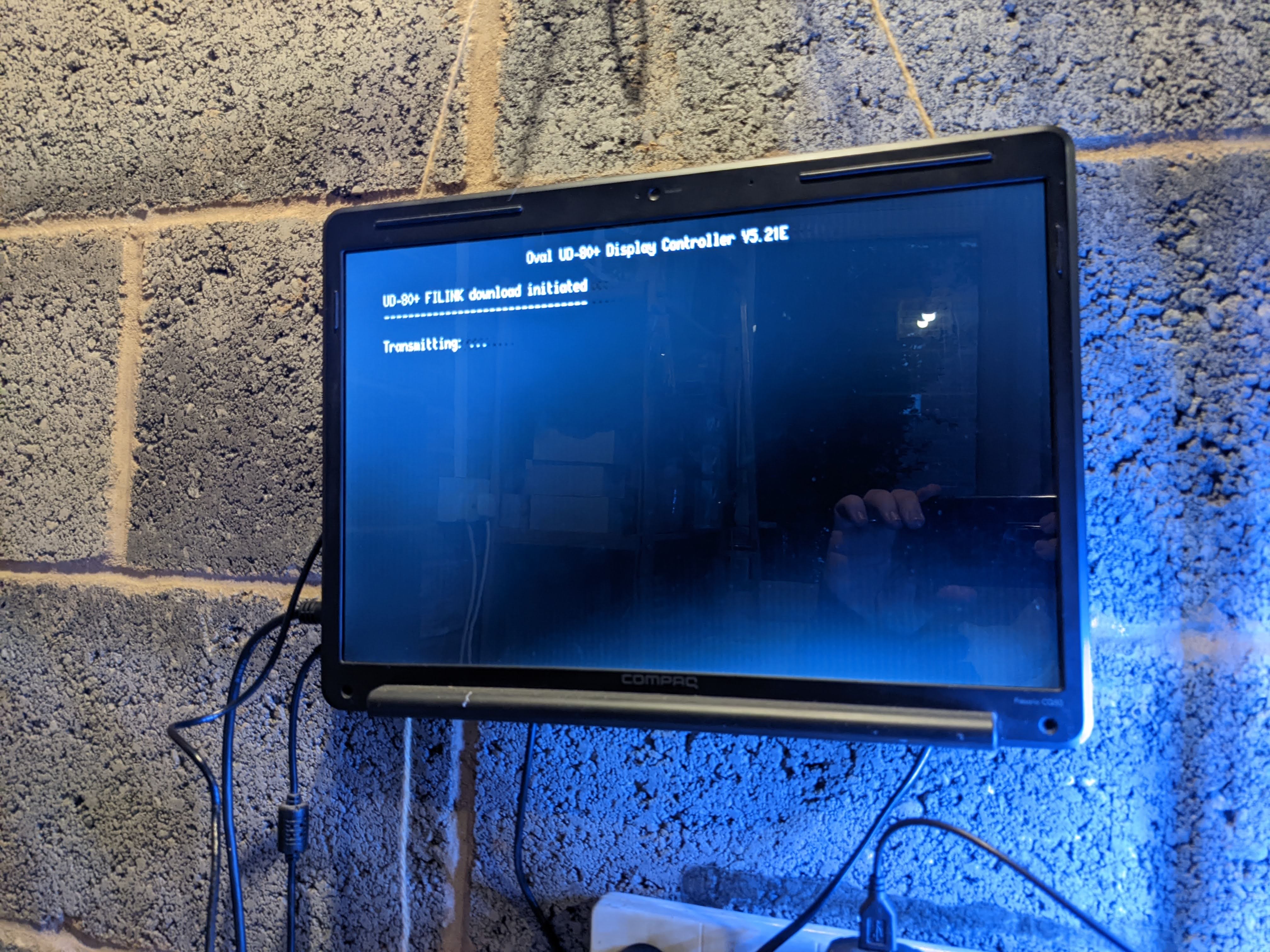
Step 8 - Press the button on the front of the UD-80. A 'Transmitting...' message should appear and FILINK should indicate it is receiving UD80-DRV.COM and the WSX.COM.


Step 9 - When the downloads in FILINK have completed quit back to the menu and run the UD80-DRV.COM file that will be shown in the A: drive.


Step 10 - Switch the UD-80 off then on again to reset to 'normal' mode. A message should appear indicating that the driver is resident and can be cleared by a 'Reset'.


At this point anything that is typed on the PX-8 will appear on the monitor connected to the UD-80. In the event that the PX-8 manages to get back to it's default menu just press 'Esc' to return to the CP/M prompt and the UD-80 will spring back into life. Note that some 'garbage' appears at the top of the screen when the PX-8 returns to the menu with the UD-80 driver active.

Note garbage at the top from the PX-8 menu


During the use of this device I did have some situations where the UD-80 and PX-8 got out of step. A quick switch off and back on of the UD-80 normally resolved things (the more things change, the more they stay the same...).

So, there you go. A slightly dull but informative post for anyone with an Oval Automation UD-80 serial display adaptor for the Epson PX-8. I promise I'll stop going on about it now.


Friday, May 06, 2022

Read. The. Freakin'. Manual.

Those of you who know me will know that I am a bit of an idiot. Not as much as the young man who just rode past my house on a bike, on the wrong side of the road, busy looking at his phone. But a bit of an idiot nonetheless.

The PX-8 came with a massive amount of stuff and the donor had mentioned the documentation that he provided with it included the technical manual etc. I didn't remember seeing it but while I was tidying up the workspace (which does happen every now and again), I came across a non-descript folder that had an Epson printer manual tucked into the front cover. It was the documentation. Original documentation. An original Technical Manual. With A3 schematics and everything. Nice.

But most importantly, it contained this:


Is this the info I need??


YES! The Holy Grail!
UD80 I/O Port Pinout!

So, after looking at this innocent piece of paper I realised that my efforts to get the UD80 to work were never going to work, because I was connecting up the wrong wires (I was trying to use DTR and DSR). As mentioned above, I am an idiot.

There are five wires, and they are actually:

  • Ground
  • TxD
  • RxD
  • DTR (Handshake in)
  • CTS (Handshake out)

More importantly, the pin numbers are specified at the UD80 side! 

A quick re-configure of the cables and....


Correctly wired up.


....no difference. I did see that if I try to send the B:WS.COM file to the UD80 I actually got 'R's instead of garbage. This is good though, as it is the FILINK program indicating it's waiting to send a file. Obviously, we're waiting to receive a file so the UD80 isn't listening.

Then I remembered the push button on the front. I pushed it. No difference. But was the switch actually working? To cut a long story short, it wasn't really. It had a resistance of over 50 ohms when the switch was pressed, which is probably not really what a push button switch is supposed to do. To get around this I soldered a couple of wires to the bottom of the original switch, fed them through the hole in the front and attached an Acorn Electron keyswitch (not a pristine one I should add).


A bit Heath-Robinson.
Electron keyswitch at the end of the
red and black wires.


After booting up the PX-8, connecting all the cables, switching the UD80 on and firing up FILINK I got... Nothing. 

Then I remembered and pushed the button. *DOH*  And, would you believe it, this is what I got:


WHAT??

It only bloody works!

I was so surprised it worked I hadn't made a note of exactly what I'd done. In my haste I also managed to download the WSX.COM file and copy it over the UD80-DRV.COM file. So I had to go back to the beginning and try again. 

To say this is finicky is putting it mildly. Everything has to be switched on in the right order, at the right time. I can successfully download the UD80 driver to A: but it tries to overwrite the UD80 driver with the WSX.COM file. If I stop it and try to give it another name I get 'ERROR' on the UD80 although it's probably because it's just sending it and doesn't expect me to get in the way trying to find the 'X' key... (Of course, it turns out that I don't need to enter a filename and, if I don't, then the files are received as they are named from the UD80 ROM. Doh.)


ERROR - Also out of focus...


Once the UD80 driver is run, there doesn't seem to be anything to do and the output of the screen is sent to the UD80. It's confusing at first because the PX-8 has a 'menu' system it runs by default and the UD80 sees this as graphics characters. Pressing 'Esc' switches out of that and brings the display on the UD80 back to a system prompt.

And from there, it looks just like any other early 80's PC like computer running CP/M. 


The PX-8 'CONFIG' program

WordStar but without the extension installed..

Basic operation - note garbage at the top from the 'Menu'
system on the PX-8

Running a DIR and STAT command from the command 
prompt. Looks almost like any early PC like computer.

Of course the first thing I did after recovering from the shock, was try the games. They don't work. Boo! The UD80 automatically switches to 40 column mode and instead of graphics characters there's a random selection of letters and block graphics. I didn't think that they would work properly but it was worth a go. :)

Things left to do:

1) Document exactly what I need to do to get this running properly. The big issue here is that there are no batteries in any of this kit, having been removed for preservation reasons. As a result a lot of what's needed to configure this setup would only have needed to have been done once back in the day, as the resulting config would be retained in the RAM/RAMDisk. Everytime I turn the PX-8 on it's like I'm turning on a brand new unit with no non-volatile storage. If I leave the mains charger plugged in then it keeps the settings and the driver file stays in memory but as soon as it is unplugged they are gone. But this is a minor inconvenience to ensure that this system does not die from battery vomit...

2) Get some proper photos of everything and organise the ROM dumps. There's a superb resource on the PX-8 here and the curator of that site might find this sort of stuff useful.

3) Try the output in a different telly*. That monitor screen and driver really does NOT seem like that composite signal.

4) Build an RGB cable. I wonder if it will work with SCART..?

So, finally, a success. And one that I'm really pleased with. Without the documentation from the previous owner this would probably have been sat in a box for another twenty years having never been used again. As the title says, you should always Read The Freakin' Manual!


*BREAKING NEWS

I tried the output in a different TV and the output is still not great, so it's just the way it comes out of the UD80. So, time to try an RGB cable...

Hmmm.


Sunday, April 24, 2022

Lines! So many lines!

The PX-8 display is, you might say, not really up to modern standards. It's an eight line LCD with no backlight and only a contrast control to try and make it easier to read. Even back in the day, the display was criticised as being difficult to read, partly due to the dim display but also because the text does not have 'true descenders' i.e. the letters like 'y' are contained on the one line and don't dip into the line below. Apparently, this makes things difficult to read. The reviewer clearly had never used a ZX Spectrum... But I digress..

Not exactly 4K..


To get around this a company called Oval Automation came up with a clever box called the UD80 to extend the PX-8 display to a monitor that allowed for 40 or 80 columns (the LCD is actually 80 columns anyway) but with 24 lines of text. Ooooh! A whole 24 lines of text! Luxury.


UD80 on the bottom
DS8 on the top


The unit itself is in a very pleasingly 70's brown with a military grade metal case held together by four screws. There are three connectors on the front as well as a recessed button (the button may once have had a plastic insert that has since been lost but I don't know for sure). These are:

Serial I/O - 8-pin DIN connection to the back of the PX-8
RGB - 5-pin DIN RGB connector
Aerial type socket - this is actually composite (more on that later) and not RF

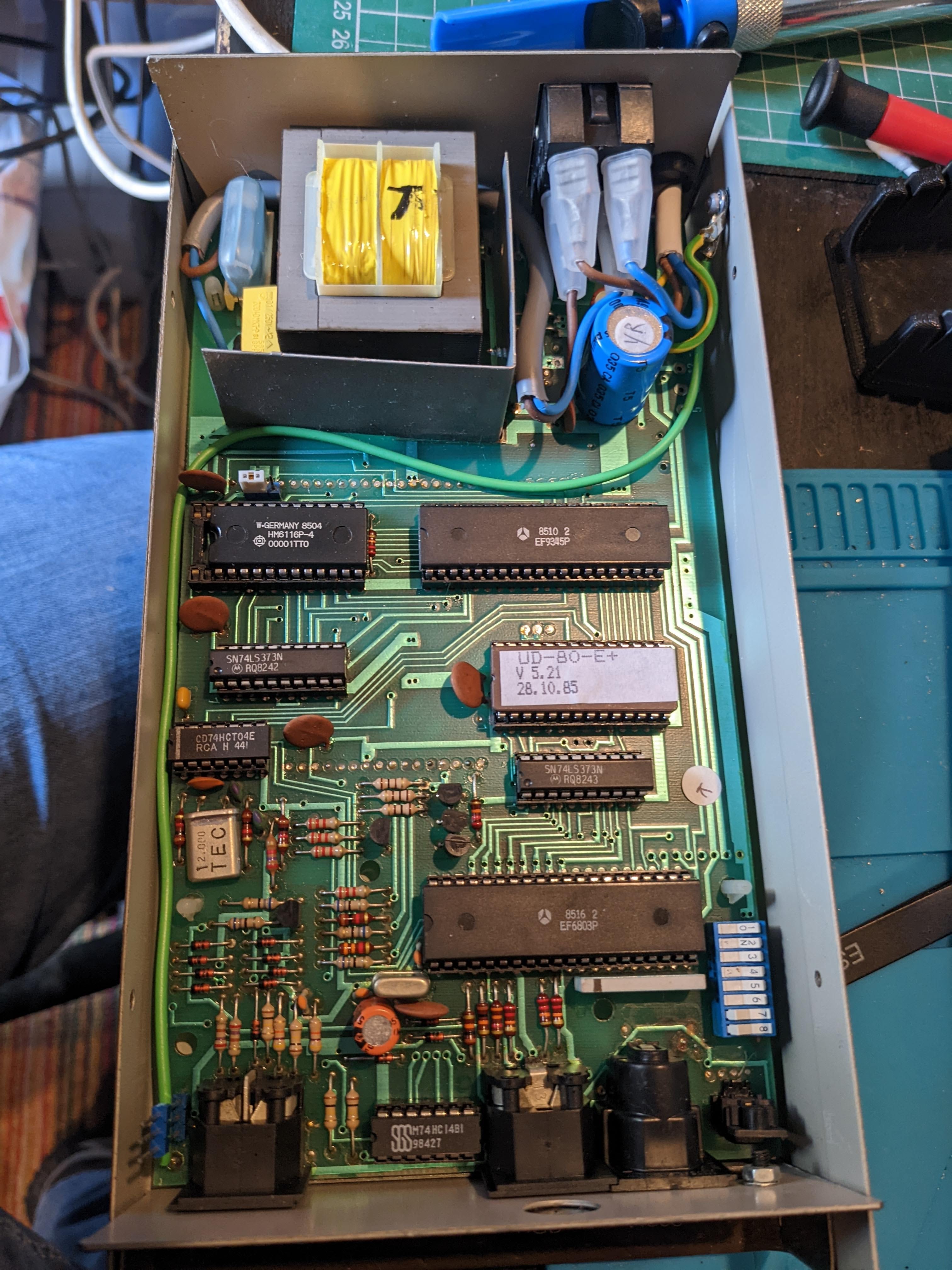
Opening the thing up shows a fairly chunky transformer which makes a period correct 'buzz' when switched on. It also means I need to be careful about touching anything that could make me very sad while it is on.

What's in the box??


Inside there is a Thompson EF9345 'semi-graphic microprocessor' that can generate 8 colours with 128 alphanumeric characters along with 128 'graphic' characters. By todays standards it's vey primitive, but for 1985(ish) it was a definite improvement over the PX-8 LCD display. Also inside are an EF6803 8-bit microprocessor, derived from the 6800 (the Dragon 32 used the 6809 of similar stock).

The question is, does it still work? After a couple of quick electrical safety checks I plugged it in and turned it on. No bangs or flashes. No magic smoke. So far, so good. Now to see if anything was actually coming out of it. So I took my oscilloscope and probed the 'Video' output. 


Is this a video signal I see before me?


With the scope showing what looked like a video output I went looking for a cable and found one in the bin (really) with the correct aerial plug on one end and phono on the other and plugged it into the back of my tiny Sony TV.

Yes! A video output! A very SMALL video 
output!

Success! But its a bit small. As it's composite I tried plugging it into my recovered laptop LCD panel. The composite on the control board isn't the best but it is much bigger than the Sony TV and it's clear to see that the unit is up and working.

That's bigger. 


Then I hit a snag. In the huge selection of cables I'd been given with the PX-8 I didn't have an 8-pin DIN to 8-pin mini-DIN that I would need to connect it to the UD80. 

After a lot of detective work i.e. I found a 5-pin DIN to 8-pin mini-DIN that is used to connect to DS8 to the PX-8 (did I mention the DS8 yet?), I think I have managed to establish that out of the 8 pins on the UD80 DIN connector, only five are actually needed.  These are:

  • Gnd
  • RxD
  • TxD
  • DTS
  • DSR

I did think that I could make a 'straight through' cable with all the parts I have, but a quick investigation of the port on the front of the UD80 revealed that pin 2 is GND. This is NOT the same as pin 2 on the PX-8 which is actually TxD. Other 5-pin DIN applications seem to fairly consistently use pin 2 as ground so the UD80 is possibly still wired up a standard way. I just don't know which of the other pins are which. Dangnabit.

But there's another issue. After an initial panic that I did not have the relevant driver file available for the PX-8 (which is called UD80-DRV.COM) I realised, after a couple of people prodded me, that this file is already in the ROM on the UD80 and using the FILINK app on the PX-8 I should be able to get it to download. I even checked that it is by dumping the ROM and having a look!

ROM Dump

Sadly, even though I can run FILINK I have no idea what I need to do to prompt the UD80 to download the driver. I have tried probably a few hundred combinations of the cables into the UD80 with limited success (although it does display some garbage with some combinations) but without the actual instructions on what to do in FILINK it's all a bit moot. Sad face.


Garbage - but it's displaying something!


UD80 end with 8-pin DIN to breakout


Breakout with one of hundreds of
combinations installed


PX-8 end


But, on the plus side, I have something that is so incredibly rare that if you search for it on Google, a lot of the top results are my posts on Twitter! And it does look like it would work, if I could find the step by step instructions..

One to re-visit.

More photos for anyone Googling:

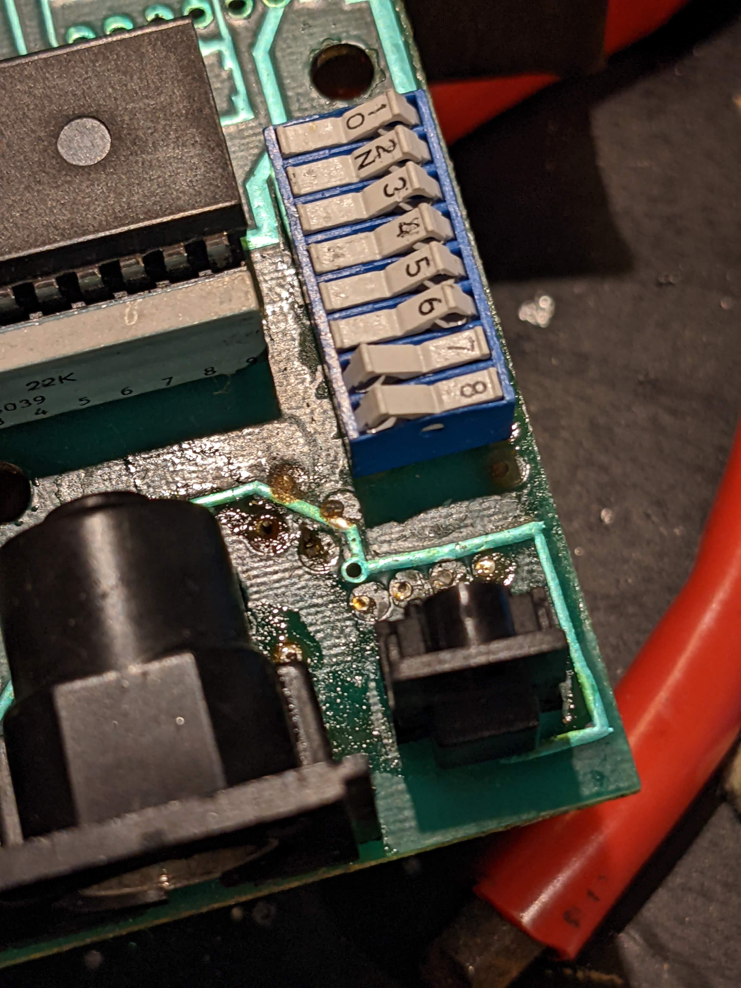
DIP switches - changes things like 40-col or
80-col mode, background colour etc

Connections through DS8 switching box

EEPROM, video controller and 6803 CPU

Bottom of UD80 board

8-pin DIN lower left of board

Video RAM upper right of board

RGB Connector centre bottom of board

DS8 Switchbox with a bit of a design flaw!
Case screw screws into the cap!

Bottom of DS8 board. Pure art.

Screwed cap replaced.

Two units together.


Friday, April 15, 2022

PX-8 - It's not all bad..

With my escapades ongoing with the PX-8 RAMDisk you'd be forgiven for thinking that the thing is cursed. Of course it isn't because a) it was free, nothing that is free can be cursed, and b) curses aren't real.

The PX-8 has two slots for ROMS. The ROMs fit into little carriers that I shall call pods because it sounds cool to say 'ROM pod'. So there. These pods contain additional applications to run on the PX-8 which could be anything from a word processor such as WordStar to a diary or calculator. The pods can also accept EPROMs of different capacities and this unit came with a bunch of them.


Pod, pod, pod.

Pod, pod, pod, pod, you get the idea.

The first thing to do with these is to dump the ROMs so that I can re-use the chips for other things but easily restore them to their original state if I need to. This is particularly important for the DS8 video output boxes that came with the PX8 which are probably the rarest things I currently have in my collection. (I don't know if they work but if I don't plug them in and turn them on, they might..) Reach for the Dataman S4!

I'm not sure if I mentioned but I modified the S4 to run directly from a mains adaptor by hooking up the battery terminals directly to a modern power supply. This removes the need for an internal battery which also removes the risk of a damaging leak but has the drawback I have to re-load the 'library' of supported EEPROM devices every time I want to use it. A minor inconvenience.

To get going I just boot up the Dataman software from 2003, which works flawlessly with Windows 10 if you were wondering, and just select 'Download Library'. Then I select the library file, which is still available from the Dataman website, and then wait a couple of minutes. A message 'START LIBRARY?' appears on the display and by pressing 'ENTER' everything is ready to go.


Library 3.00 ready for action

To select the correct chip type it's a simple matter of pressing 'PROM' then using the up/down arrow keys to find the right manufacturer then the left/right arrows to select the right chip. Easy peasy.


This EEPROM is a National Semiconductor.

So, what to do. I take one of the dumped EEPROM chips and a PX-8 ROM file downloaded from the most excellent resources located here and here. How do I get it on to the chip? Well, first of all this is a UV erasable EPROM so I can't clear it with the S4, I need some other way. The datasheets for EEPROMs will normally give an indication of what's required and in most cases it's a blast of UV light at a wavelength of 257nm (nano metres) for about ten minutes.


Intel D27256 EEPROM
Note the window where UV enters

I have to tell you now that the EEPROM erasers that are available on various auction and other retail sites are complete garbage. I shall quote from one review of a unit that someone purchased from a well known site:

"This is basically a 'use at your own peril' device. It's really badly made with gaps all around the base and top cover. I'm sure if Her Majesty's Customs had anything to do with this, they'd incinerate them on sight. ... although it feels as if there's a reasonable chance they would do that on their own.

The warnings that come with this are crazy; maybe because they're in broken English. The gist of it is 'turn it on, run and don't look back'.
...
Having read the other reviews , the first thing I did was take it apart and put in a new power cable and a fused UK plug. The one you're replacing is terrible - there's around 5 threads per core.
...
After leaving on for seven minutes (with an extension lead going to the device, which I sat in a bucket with wood over the top. If I had an x-ray screen I would have probably gone behind that too) it did actually blank the AMD 27C400 inside.

I didn't really doubt that it would, I just expected it to explode or at the very least start smoking as soon as I flicked the power on.

So? If you need to blank an eprom or two, then go for it, but, take enormous care with this piece of junk."

This was not what I would call a 'glowing' review.

But there is an alternative. In a bizarrely 'Hitch Hikers Guide' turn of events, I purchased a 'Phone Sanitiser'. This is basically a white box that you put your mobile phone into and, for ten minutes, it bathes your phone with UV light at 257nm, to kill bacteria and leave you with that smug feeling that you won't catch any virulent diseases while posting cat pictures on Instagram (or whatever the kids are doing these days).


You won't be wiped out by a virulent disease contracted
from a dirty telephone.


But did you see what it does? It emits 257nm light for ten minutes. And it only cost me £13. And it's a surprisingly high quality unit. There is mention of 'Samsung' on the box and in the small manual it comes with but it's not directly made by Samsung. No matter. It does what I need it to do.

Opening the lid reveals two small tubes, one at each end. By resting the EEPROM with the window directly facing the tube, it is completely erased in ten minutes. Blank EEPROMs are full of 'FF's which indicates they're ready for writing. Nice. I shall probably look at designing and 3D printing something to hold the chips more securely in sanitiser in the future. 


Open sesame..

FFs sake.

So now I have a blank EEPROM and I want to write my downloaded ROM to it. In the S4 software I just select 'Transfer > Send file (PC>S4)' and select the ROM file. The format of the file can vary, mine is a 'HEX' format, but the software supports at least four different formats.

After a minute or two the transfer is complete and on the S4 software I select 'Memory>Checksum RAM' to check what the value should be, then 'Device Pretest' which should tell me the EEPROM is blank. Then I can 'Burn' which copies the contents of the S4 RAM onto the EEPROM. Once complete I always do a 'Device>Checksum ROM' to make sure it matches the RAM checksum from earlier. 

In theory, the EEPROM should be ready for installation into the bottom of the PX-8. The little carriers aren't essential and the EEPROM can be fairly easily pressed into the socket without any problems.

Does my new ROM work?

Yes. (Sub Zone)


Yes. (Tower)


Yes. (Tank Attack)


Yes. (Snake Pit)


These are about the only games for this system (I do have a version of Othello I want to try though) and they all work perfectly and are surprisingly fun, even if my aged hands start to hurt on the cursor keys after a few minutes. 

Now, if only I could get that RAMDisk to work...