Saturday, June 23, 2018

A Brace of CPCs..

That wonderful site, eBay, can be a strange place. Sometimes it's possible to find a bargain but most times it's basically someone either:

a) trying to rip you off by demanding ten times the actual value of an item - "it's old so it must be worth a fortune, right?"

b) trying to scam you - "please post to my brother-in-laws cousin in North Africa and I will send you twice what you asked by cheque"

c) selling broken crap - "sold as untested as I don't have the TV cable that I could get for £1 from Wilko 'cos I know my dog peed in it and it's never gonna work again.".

This time, I struck lucky. For a modest sum I bought a job lot of computers which included:

1 x Commodore Plus 4 with cassette drive, joystick and manuals
2 x Amstrad CPC 464

eBay Score!

There were no power supplies with any of them but, as luck would have it, I managed to acquire a Plus 4 power supply which could have been problematic - but the Plus 4 is another post to come. For the CPCs I just needed a 5V, centre positive supply which I happened to have already, and a video cable.

So, the units themselves. They look like they've been in a very dusty, dirty environment for a very long time. They may have been in a barn given the amount of dirt (not dust - actual dirt) that caked every inch of both of them.

A Bit Dirty
Yep - Dirty.

By peering into the user port (and then I took them apart) I can see that they are both slightly later versions of the CPC 464 as the motherboards only occupy half of the enormous case. The joystick port and headphone socket are at the end of the case too, rather than on the back. The motherboards are very slightly different to each other though. One has a 40007 ULA, the other a 40010. The 40007 is heatsinked and is located in the 'other' space for a chip on the board. In the photo below, there is a big gap with the outline of a chip just above the 40010 ULA - this is where the 40007 is on the other board.

Does this look big on me?

One of them has been clearly dropped at some point too as there is damage to rear of the case at the cassette recorder end (also visible in the photo above).

A very brief CPC464 history. Alan Sugar saw the computer market and wanted in. Amstrad released the CPC464 on 12th April 1984 following a bit of a false start. But with typical AMS business sense he made sure that there was software available and the machines just worked out of the box (unlike the Sinclair QL). It's worth reading the entire article linked to above. It's a surprisingly interesting read.

Clean up time. I decide to start with the non-damaged unit (comes with the 40007 ULA). Dismantling these things is straightforward. Six screws in the bottom, lift up the top carefully and remove the cable from the motherboard and the keyboard connections. Early 464s had a cable to connect the keyboard but later ones switched to using membranes, and it's this type that I have.

There are another six screws holding the keyboard to the top case and six more holding the motherboard to the bottom case. Amstrad must have over-ordered on screws...

Once the keyboard is free of the case, it's tempting to just start pulling keycaps off. Don't. On the back of the assembly are small black clips. Press on these gently to release them from the metal back and, once they're all released, the back plate and membranes can be removed leaving just the actual key assembly itself. Turn it over and it becomes obvious how to safely release each keycaps with little chance of breaking them. If you just start pulling key caps you WILL break them. So don't. 😀 Using a finger to hold one clip, use a screwdriver to gently push the other. The keycap should just pop out. 

Membrane and Backplate

Keyboard Unit (and glasses)

Be careful, there's a spring on the other side! Don't lose any of them! This style of key return is similar to that of Amiga keyboards. The main difference here though is that each key has a smaller spring embedded in it which is what makes contact with the keyboard membrane. These smaller springs are fairly well secured in the keycaps though so you shouldn't lose any of them. 😀

Keys and Springs - Don't Lose Any...
Yuck.

With all the keys removed, I washed the black plastic section with mild soap and water. It was, to put it mildly, a bit grubby.


That's Better.
Then, each key was washed and dried by hand. And there's a lot of them. It took about an hour to do all of them but the results are great.


And....relax...

It's worth noting that there are several keys that have metal bars attached to them, notably the 'shift' keys and the space bar. These need care but are relatively simple to remove. Press the key from the key side and on the back, gently push the bar out of its clips. If done right it shouldn't need too much pressure. Re-fitting is just the reverse procedure. Drop the clip into roughly the right position, press the key and gently ease the bar under its clips. Simples. 

Next, the case sections need washing. To do this I removed the motherboard (duh!) from the bottom section, and the tape drive, volume control, power switch, power LED (might be glued in - be careful!) and speaker from the top. There's another load of screws to deal with here and, if you have one of these computers and decide to do something similar I would recommend you take a picture before you start so that you can see the routing of all the cables when you have to put all those pieces back together...

Bath Time!
Once the case had been thoroughly washed down with a mild detergent and a bit of help from a nailbrush, they were toweled down and left to air dry.

End of part 1. In the next part, I put it all back together to see if it works...


Sunday, June 10, 2018

Re-capping My Buddy & Other Mods

My little buddy. He's had a new RAM chip, diagnosed thanks to the great Smart Card V2 available from retroleum.co.uk and now he's working. Except for the keyboard..

Anyway, as is fairly typical for this age of equipment a lot of people recommend that the capacitors are replaced. My long time readers may remember when I re-capped my (now sold) Amiga A1200 a few years ago. The principle is the same. Electrolytic capacitors dry out and become faulty or, worse, leak corrosive electrolyte over the delicate motherboard tracks.

So, if it's old tech, replace the caps. Not everyone subscribes to this view, but I do. So there.

The nice thing about the caps on the Spectrum is that they are all through-hole caps. None of that awkward surface mount nonsense here. This is 1982. The only slight snag is that most caps nowadays come in radial form i.e. the leads protrude from the bottom of the capacitors can. In 1982 most caps were axial i.e. the leads came out of each end. This makes finding exactly the right caps a bit more problematic but not impossible. In any case, there are several retro suppliers who will provide a made up kit of either axial or radial caps, such as the aforementioned retroleum.co.uk. :)

My buddy's main board is an issue 2 which has a few additional things to consider other than just doing a one for one swap of capacitors. To start with, the capacitor at position C46 is labelled incorrectly on the motherboard and has to be installed the wrong way around (according to the silkscreen). C46 is the first horizontal cap on the board on the top right of the picture below - just above the keyboard connector.

C46 Error - Don't Forget!

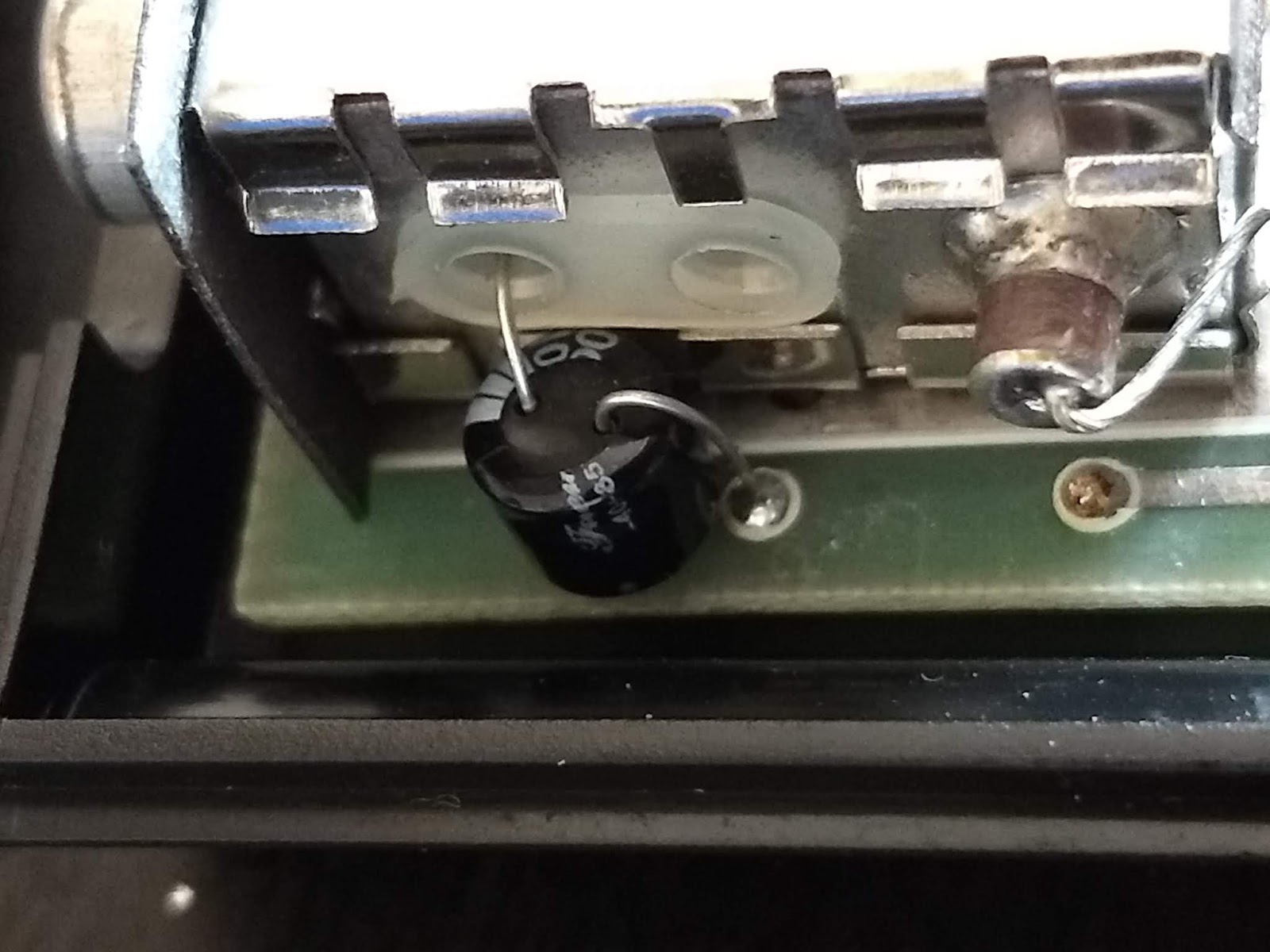
Secondly, on the issue 2 boards there was an engineering improvement made to the DC-DC converter circuit which required an additional capacitor to be added and a resistor replaced. After a bit of 'origami' with the cap leads, I managed to get it looking OK. Also note new resistor at R60.

Power Circuit Modification - Nice.
Finally, two of the caps are located VERY close to the heatsink. The recommendation is that these are installed with a higher temperature rating than the usual 85 degrees. Axial caps are not available for the required values so radials are used and installed in the same way that Joulespercoulomb installs his.

C27 - 1uF Rated at 105 Degrees

C47 - 22uF Rated at 105 Degrees

In both cases, additional sleeve is added to the positive leg to prevent any accidental shorts. Double nice.

As a last touch, I decided to do a 'proper' job of the composite mod too. This meant that I removed the straight wire from the modulator that was connected to the composite signal from the board and replaced it with a capacitor.  This should give slightly better results - although composite signals are never the best...

Improved Composite Video Mod
 And with that, the main board refurb is complete for now. There might be scope to replace the ULA with a new modern version (called Nebula, available from - you guessed it - retroleum.co.uk) or possibly add some heat dissipation to the ULA as it does get a little warm. The only other thing that could be done is to replace the 7805 voltage regulator with a modern switched supply. These are relatively cheap and run significantly cooler than the 7805s.


Refurbishment - Done. Probably.
Now all I need is a working keyboard...


Friday, June 08, 2018

ZX Spectrum - My Little Buddy

In 1984 I remember coming home and seeing my Dad reading a book about the ZX Spectrum + and my brother and I both asked "Are we getting one then?" to which my Dad replied, "Go and look in the other room."

Sat on the table was a shiny new ZX Spectrum +. To cut a long story short, my brother and I played many, many games for many hours. My Dad spent many hours tinkering (much to my Mum's annoyance) and, at one point, managed to break the copy protection on Jet Set Willy II, purely because of the stupidly huge copy protection foldout card...

Anyway.

As time went on I became interested in other computers (the Amiga by any chance?) but I always remember the happy clicks that emanated from the keyboard whenever any key was pressed.

So in 2018 I went and bought a ZX Spectrum 48K with rubber keys because, why the heck not? As with most eBay purchases, the unit was sold as 'untested' but did come in its original polystyrene but no outer cardboard box. It also has the original manuals - which, to be honest, are far superior to the Spectrum + documentation - and the original power supply.

Before I did anything I went and watched the videos by the excellent Joulespercoulomb. In particular, he has produced a video that details the tests to undertake before plugging in the Spectrum. There is also a very useful video on power supplies.

Original Power Supply 
This supply is original and marked as 'UK 1400' which means that it should deliver 1.4amps. Other supplies might be marked 'UK 700' which, as you might guess, delivers up to 700mA.

Power Supply Opened Up for Testing
Opening up the supply reveals just how simple (and cheap) these supplies are. It's basically a transformer with four diodes and a couple of smoothing capacitors. That's it. The DC 5V that they produce is notoriously 'lumpy' and in my unit, generates an almighty coil whistle. But I'm getting ahead of myself.

I checked the diodes in circuit and they all seemed OK. I checked the transformers windings to check for short circuits etc. Also, no problems. This supply should be OK to use. And one final point. The Spectrum expects the centre pin to be NEGATIVE. The modern supply I have has detachable barrel connectors so I have to make sure when I plug it in that I have it the right way around or I may release magic smoke.

To the main event. There are five screws in the bottom of the Spectrum's case. Once taken out the top lifts off but remains connected to the main board by two connectors from the keyboard membrane. In my machine, the membrane was intact but in a sorry state.


Left Connection - Bent and Broken
Right Connection - Also Bent and Borked
I suspected that the keyboard wouldn't work even if it booted correctly. This is fairly standard for these machines but new membranes are available from various places. No biggie.

Can you hear me, Mother(board)?

The main board is an Issue 2 which is easily identified by the location of the voltage regulator heatsink being on the bottom right. Later boards moved this to the top, near the edge connector. There is also a factory mod on the CPU with a transistor mounted across it. This was added due to a 'bug' (or feature) in the ULA - Uncommitted Logic Array which meant that the system would be too aggressive when it thought that RAM was being contended between the CPU and ULA, causing speed and timing issues. Later boards incorporated this update onto the actual board.

Before I could do anything I had to modify the TV Modulator. No-one uses RF these days but, as luck would have it, by disconnecting two wires and soldering the end of one of them to the centre pin of the modulator's connector, the Spectrum will output composite which most modern TVs (and my hacked display) will accept. This is actually a quick and dirty way to do this and I will be re-visting the display quality in a later post.

Anyway, the moment of truth. Does it boot and display the (C) 1982 Sinclair Research message?

No.

Broken. Sad Face.

Bugger.

Fortunately, I have a neat device called a Smart Card V2 from retroleum.co.uk (a site well worth visiting if you like the Spectrum). This device allows you to load games from Micro-SD cards but also includes a diagnostic ROM. This was what it said about my little buddy:


Tell me what's wrong Doc...

So, U19 is suspect. This is one of the upper RAM chips. Fortunately, our friends at retroleum.co.uk had some in stock so, for the bargain basement price of £1.25 I ordered another RAM chip. Time to get the soldering iron out.

Cheap but Effective
 First, I had to remove the old chip. This involved using the iron and a desoldering tool. Loads of videos and tips exist for this online so I won't go into too much detail. The tracks are more delicate than I'm used to with other systems such as the Amiga A500 but, with a bit of patience, I managed to get it off without issue.

The new chip went on without any problems too. I used leaded solder as supplied by my Dad. The solder must be 30 years old but is great quality and works a treat.

New RAM Loveliness


The more observant may notice that I mounted the new RAM chip directly to the PCB like the others. I'd like to say that I didn't put it in a socket because it would spoil the aesthetic appeal of the original circuit board design. Actually, I didn't have any sockets.

Old Broken Chip - Boo!

So, does it work now?

Anxious Wait

Now that is a result. I can't do much yet because of the knackered keyboard membrane but the motherboard is healthy now. More next time!


Thursday, June 07, 2018

Plus 4 Power Supply

A departure. This is not about an Amiga but it IS about a Commodore machine, or at least, a part of a Commodore machine. On the way to me (eventually) will be two Amstrad CPC 464s and a Commodore Plus 4. None of these machines have power supplies or other bits but that's no big deal these days. Except for the Plus 4.

The Plus 4 is an odd machine. It started life as a 'budget' series of computers from Commodore that were intended to compete with the likes of Sinclair's Spectrum. The boss of Commodore, Jack Tramiel was determined to get that part of the market but, sadly, his sudden departure following a disagreement with Irvine Gould (Commodore's main investor) left the ship without a captain.

What followed could have come directly from a Dilbert cartoon. The 'low cost' range was 'got at' by the marketing department. Changes were made to the design. All of a sudden, instead of a budget range of computers, Commodore released a parallel range of computers that were incompatible with its flagship computer which happened to be selling very well - you might have heard of it, the Commodore 64 - and cost almost as much. Genius.

Anyway, the machines were in themselves OK. Not great but solid 8-bit machines, the top of which was the Plus 4 (others in the range are the 116 and Commodore 16 which is not a cut down Commodore 64 - thanks CBM marketing!). The name came from three plus one utilities that were built into the machine, requiring no disks or cartridges.


Plus 4
Image from Wikipedia
So, on the way (at some point) is a Plus 4 but without a power supply. This machine uses +5v DC and +9v AC on it's supply. Not only that, but at some point early in its production run, Commodore changed the design of the power socket in the machine from the standard Commodore 64 type, to a square DIN style - similar to the Amiga but with only four pins instead of five. These DIN plugs are impossible to source now whereas round DIN sockets/plugs are still widely used. Commodore strikes again...

The Infamous 4-pin DIN. Grrr.

Fortunately I managed to source a Plus 4 supply which came to me as untested. Naturally, I was a bit reluctant to just plug this in and switch it on without looking at it a bit. Getting into it was tricky a they are sealed, but given its age, it has clearly been through some punishment and the bottom came off surprisingly easily...

A Potted History - geddit?
The first thing to notice was that the transformer is potted i.e. the case is filled with epoxy to prevent 'meddling'. The thing I was interested in, though, was the little board at one end. This board contains the circuit to convert 9v AC to 5v DC, including a bridge rectifier and 5v regulator. Unfortunately, the centre pin of the regulator had a bad solder joint and, in the process of poking it, the bit of track with the hole in came off and disappeared. Crap.

I also noticed that the circuit board under the diodes was darker than the rest of the board. This indicates that the board has seen some heat. This is most likely just a cumulative affect of being on and off over the previous 33 years - this supply was made in 1985! I actually went as far as to remove the diodes in the rectifier from the board, test them and then put them back. All were OK.

Diodes - All checked OK
To be sure that the regulator was working I removed the main circuit board and soldered wires to the three legs.

Regulator - Temporary Wires
9V Battery
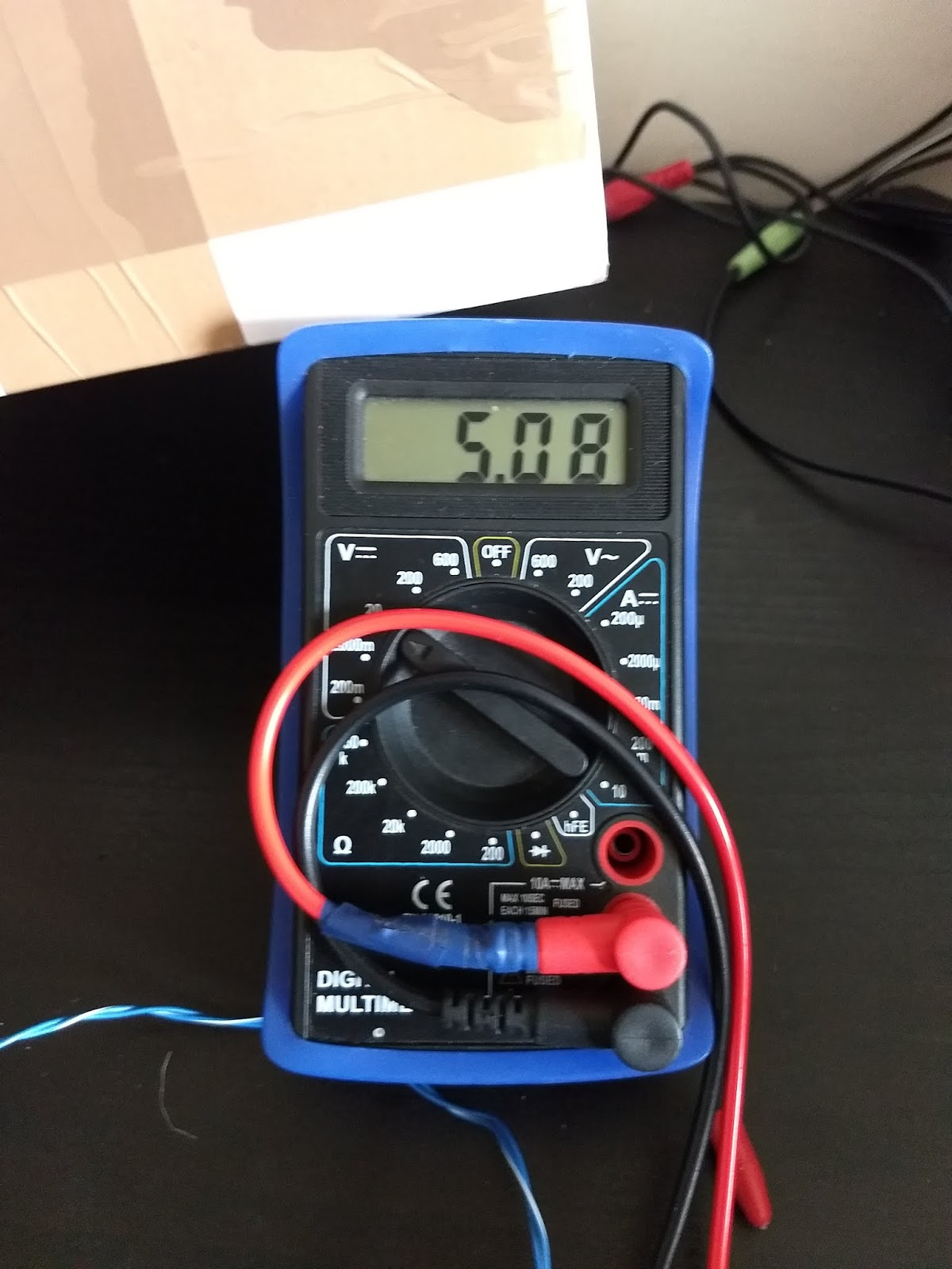
On pin 1 and 2 I applied 9v from a simple 9v battery. On pins 2 and 3 I connected my multi-meter to check the output voltage. And, joy of joys, it read a rock steady 5v.

5V From the Regulator - Nice.

After putting the board back and putting in a repair on the, ahem, missing bit of track for the regulator, I realised I hadn't tested the fuse. Trying to get the fuse out proved harder than I expected. It took a lot of twisting and pushing and releasing and more pushing and twisting before the fuse holder would come out of its housing. Even then I had to pull it out with pliers. For some reason it was caked in a white residue, possibly grease of some sort? It took a bit of effort with some isopropyl alcohol and cotton buds to clean it all out. Now it's clean, the fuse pops out when requested, just like it should.

Fuse.

Finally, I put the case back together, temporarily stuck with super glue and cable ties to prevent any accidents. Then I tested the output voltages at the plug end and, to my relief, there is a steady 5v DC and 9v AC on the correct pins, so, as far as I can see, this power supply is ready for (limited) action. I don't intend to use this permanently as there are easy DIY ways to create a more stable, modern supply. But for now, this will be OK.

I just need the Plus 4 to plug it into now...

Friday, June 01, 2018

CD32 Joypad Find

Some time ago you may remember I posted about using an old PC controller as a CD32 controller with the help of a clever board and some slightly dodgy soldering skills. Imagine my surprise when I received a text from Child 1 saying he'd found a CD32 controller going cheap and would it be useful?

Yes. Yes. YES. YES.

So, after texting him, telling him to buy it immediately, I also asked if he could send a photo so I could see the general condition of it.

This is what he sent.

O. M. G.
Oh. My. Goodness.

This is not an original Commodore CD32 controller. This is a Competition Pro CD32 controller. You might remember I mentioned my previous blog post about controllers. In that blog I talked briefly about the Competition Pro controller and I referred to it thus:

"There are other options such as the Competition Pro CD32 controller but these are even more expensive on evilBay than the originals by an order of magnitude."

Things haven't really changed on this front with several of these controllers selling for anywhere from £50 to £80, hence my original post. And my son had just bought me one. :)  When I told him it wasn't an original he was a bit crestfallen until I told him it was way better than that. I feel I have succeeded at parenthood. :)

Anyway, I had to wait a little while to get my hands on this as Child 1 is at university at an undisclosed location. Finally, we met up with him this weekend where he handed over the controller and I (or actually Mrs Crashed) handed over the cash spent. Result.

First things first. Does it work? A simple run through the usual test disk (from the excellent Keir on the Amiga Facebook group) shows that it does. The Dpad is a bit spongy but, other than that, everything else is fine. The worlds most boring youtube video shows me in action....


CD32 Joypad Testing

So, in terms of restoration, the only things needed are some way to unspongify the Dpad and give it a bloody good clean. It is, to put it mildly, a little grubby. To clean it properly, I need to take it apart and get the case and d-pad in the sink with soapy water and an old toothbrush.

 After taking out the screws, the back case comes off easily, revealing the main board and a small daughter-board which has the contacts for the Dpad.

Back off - Daughterboard on the Right of Picture

Next, off came the shoulder buttons, the Dpad and the rubber Dpad underlay. This looks like it's seen some action and is slightly worn. This would explain the sloppiness in the Dpad but I have a solution in mind...


De-construction continues...

There are two screws holding the main board to the front case. Removing these let me take out the main board and see the switches and buttons. Interestingly, the buttons have individual rubber cups with carbon contacts which I haven't seen before. The switches are fairly standard and their contacts operate directly on the main board. 

Main Board Removed

And there are a lot of 'bits' that need to be kept safe while the major components take a quick bath..

Nobody sneeze!
After a good clean I put all of those pieces back together, but not until I found a small, perfectly sized spring, to try and solve the spongy Dpad issue. It probably came from an Amiga keyboard - there's a nice symmetry about that - and it fits perfectly underneath the plastic Dpad and just gives it enough of a lift to improve the feel.

And here's the final result, with no pieces left over:


Nice.


Wednesday, May 09, 2018

Keyboards - More Interesting Than You Think.

OK, so keyboards might not be THAT interesting.

I've been floating around the Amiga Facebook group for a while now and recently had a bit of a conversation with a couple of the guys about the different keyboards that were used on the Amiga, specifically on the A500(+).

A little bit of history. When the Amiga first launched it was known as 'Amiga'. Later, this first model was renamed as the Amiga 1000*. This model had a separate keyboard that slid neatly under the case to keep everything tidy. Allegedly, this design 'feature' was one of the reasons for the high cost of production. Another debatable point. The keyboard itself was a compact design, smaller than a standard IBM XT/AT keyboard but it was mechanical i.e. each key had a switch that when pressed sent that character to the computer. According to Deskthority.net, these keyboards were manufactured by Mitsumi. They also had the familiar 'A' Amiga keys, but with the 'A' printed in red.


A1000 Keyboard - Note Red Amiga Keys
Pic from Deskthority 
*There is some debate about this. Some say that it was always the A1000, some that it became the A1000 later to distinguish the models. I don't know the exact answer.

Fast forward a year or so. Commodore made a brilliant business decision (one of few) to release a cut down Amiga that would make it available to a much wider audience. This was the Amiga A500 which was the brainchild of Jeff Porter at Commodore. It incorporated the keyboard into the case and a floppy drive in the side in a form factor that was familiar all the way through the late eighties and early nineties. The Amiga, Atari ST and Archimedes all followed this design and it was highly successful.

From the information I have been able to find, the first Amiga A500s were actually released with Revision 3 motherboards. They also included keyboards that closely followed the design of the A1000 in that they used mechanical switches. They were actually Hi-Tek Series 725 and are affectionately known as 'space invader' keyboards. This is because, when a key cap is removed, the shape of the switch closely resembles the space invader characters from the 80's arcade classic.

Space Invade Keys
Original image from Deskthority

These early keyboards are easy to spot for a slightly fortunate reason. The plastic keycaps are made of polybutylene terephthalate (PBT) which, according to Deskthority.net is the hardest material used for keycaps. If you know anything about the Amiga you will know the problems with 'yellowing' caused by the bromide used in ABS. This doesn't happen with PBT so these keyboards make themselves obvious by being completely un-yellowed compared to the A500 they sit in. If you find an A500 for sale with an almost perfect white/grey keyboard then the chances are, it's a space invader type. They were only used on Revision 3 and some Revision 5 motherboards (Revision 4 isn't really a thing for the A500).

Another feature of the early A500s is that the case badge is moulded into the case itself rather than being a recessed plastic badge. These are known as 'chicken lips' cases since the Commodore logo looks like a stylised drawing of a chicken. Allegedly. So, the upshot of all this is, if you happen to be perusing a car boot sale in your local muddy field and happen to see a chicken lips A500 with a pearly white keyboard at a decent price it's well worth getting as it will almost certainly be a rare, early model.

While the 'invader' type of keyboard is very nice to use, and is comparable with some of the best mechanical keyboards available even today, they also had a bit of a cost problem. They were not cheap and kept the price of the A500 high. To get around this, new keyboards were developed with a much lower price point and subsequent drop in 'niceness'.

There were two main types of this reduced cost keyboard, Samsung and Mitsumi. Yes, Samsung made keyboards for the A500.

However, the Mitsumi keyboard is by far the most common used on the Amiga A500. It was so successful - if not very good to use for long periods - that the same basic design was used for the A600 and A1200 keyboards as well as some A3000 keyboards. Mitsumi keyboards use 'hybrid switches' which are basically a plastic post that contacts with a membrane that completes a circuit. A spring underneath the keycap provides the 'return' of the key when pressed. The Samsung keyboard was similar but the spring was held inside the keyboard so that the springs are under the posts rather than directly under the keycaps as per the Mitsumi.

Samsung Keycap, Post and Spring
The above pic is of a keycap, post and spring from an old Samsung keyboard. The spring is REALLY small. And to make matters worse, if you need to replace the membranes (if you can find any new ones!) then you'll need to remove the rear plate of the keyboard and run the gauntlet of losing:

a) the worlds smallest screws
b) the worlds slipperiest springs
c) your sanity when you try to put it back together

Mistumi Keycaps - Note the bigger springs
Original image from Amigos Retro Gaming
You'll notice how much bigger the springs are for the Mitsumi keyboards which you would expect would give a better feel than the Samsung but they both feel very, very similar. Also, it is surprisingly easy to lose even these larger springs when you try to remove the keycaps. They fly out at an alarming speed when the cap finally pries loose, and instantly vanish into any carpet nearby...but they're nowhere near as fiddly as the Samsung.

Neither the Samsung or the Mitsumi keyboard offer a particularly good typing experience. The keys travel a little too far, there isn't any real tactile feedback and the general feel is quite spongy and unsatisfying. Both also suffer from the dreaded yellowing mentioned above as all of the keycaps are made of ABS. Despite this, it is relatively easy to determine the make of keyboard an A500 probably has.

Any A500 UK keyboard with a 'small' return key is ALWAYS Mitsumi*. This includes all A500+ and any A500 that has the larger A500 badges rather than the small square Commodore logo. The same basic keycap design is used on the A500, A600 and A1200.

*European keyboards always had a small enter key to allow for additional language characters. I've never seen a Samsung keyboard with a small enter key but they could be out there.

If the return key is the large 'L' shaped key then it could be any of the three available types, so ask yourself the following questions:

Q) Are the keys still very white?
A) Likely to be a 'space invader' keyboard.

Q) Does it have a 'C=' key instead of the usual 'A' Amiga key?
A) Likely a 'space invader'.

If the keys are yellow, take off the top case (if you can).

Q) Does the control board have a single white membrane connector?
A) If 'yes', it's a Mistumi. If 'no' it's a Samsung.


Samsung - Dual Connector (excuse my dust)
Mitsumi - Single White Connector
If you can't take the top case off to look at the control board then look at the keycaps themselves.
The Samsung keyboards use keycaps that are more angular than the Mitsumi. The Mitsumi keys appear softer and more rounded. This may sound a bit vague but if you see the two different types together, the differences become obvious. You might be able to make it out in the two pictures above.

Keyboards. More interesting than you'd think. Possibly.


Wednesday, March 07, 2018

Yet Another A500+ Motherboard - Finale

Only two parts to this one. This is because the board is actually in pretty good condition overall. There are a couple of things.

First, the missing pads at JP7A and J9. Just to be absolutely clear, the pads were loose when I got the board. They were also like that when the previous owner got the board. Fortunately, I was on hand to sort that out with a hot metal stick and some de-solder braid and a solder sucker. Poof! They're gone! The loss of these isn't critical but does mean certain modifications would be a bit more tricky in future...

Next, the dodgy ROM. It's dead. It's expired and gone to meet its maker. It's bereft of life. It's shuffled off its mortal coil. It is an ex-ROM. I stripped down my own A500+ and nicked the ROM from that for a few tests. It went straight to the familiar boot screen with no problems. This meant I could plug in an external drive and test it with that rather than stripping down my A500+ any further. And test it I did. I ran the Frontier game demo and just left it for a few hours. No problems.


“Don’t cry because it’s over, smile because it happened.”

Next, the joystick and mouse ports had pins broken. I'm certain that one pin was missing from the joystick port when I got the board but I'm fairly sure I broke off a couple more with my incessant waggling of the mouse plug trying to get it out. Oops. As luck would have it, I have a big bag of connectors that I 'over ordered' a while ago. They're not as good quality as the originals but they fit, they work and I have plenty....

Broken ports - oh dear. :(

The first thing to do with the old ports is, rather obviously, remove them. This was a bit of a pain but not as bad as I expected. With lots of de-solder pump action, some input from de-solder braid and a lot of patience they were eventually persuaded to come out. The hardest bit is the two anchor pins which provide mechanical stability to the ports when they're on the board. The solder joints are rather large and needed a much hotter iron than normal as well as lots of suction and a big waggle to get them to release. They both came out with no damage to the board though which was a good result.


Joystick Port Removed

Mouse Port Removed

Next, I had to solder in the new ones. This was surprisingly easy. After cleaning the board thoroughly with isopropyl alcohol and cotton buds, they just slotted straight in. I soldered one corner pin first while holding it firmly to the board, then did the opposite corner. This held the thing place while I did the rest. The larger joints for the supports were also fairly simple and just needed a hotter iron and a lot (a LOT) of solder to fill the holes. Rinse and repeat.


New ports loveliness
And from the back..

I'm really pleased with how the ports turned out and the only way you can tell they're not original is because the hex screws are a different thread to the originals. This was something I only realised as I was putting them in. Oh well. You can't have everything. A quick check with the standard Amiga test disk (courtesy of Kier on the Amiga Facebook group) proved that they are working correctly.

The final repair was to the cluster of resistors and diodes in the AUDIO FILTER section of the board. The pad on the underside of the board had been destroyed so the leg of the resistor and diode was just sticking through the hole.

Pad gone - leg with no connection
To repair this I took a piece of kynar wire and threaded it through the hole. I made sure it was long enough to extend along the leg of the diode on the other side.

Kynar wire in place - to be trimmed once soldered
I carefully soldered the wire along the exposed track, making sure that wire also joined nicely to the leg of the resistor. The I turned the board over and soldered the other end to the leg of the resistor/diode combo. Finally, I trimmed off the excess wire on the underside.

Repair complete on this side

Repair complete on underside of board

And that's about it. I did a final test to check that the audio filter still works (it does) and that I hadn't broken anything else (I hadn't that I could see). Pending the acquisition of a 2.04 ROM, it currently has KS1.3 installed. Another A500+ motherboard saved and almost ready to be released back into the wild. Thanks for reading. :)