After having the PCW sat around for a while I decided it was time to get a boot disk sorted for it. The only 3 inch disk I had was actually for a PCW8256 which is not directly compatible with machine (sort of) and it certainly wouldn't boot the PCW9512. So on to eBay and, following a quick search, a correct boot disk was in the post.
 |
| A totally not AI generated picture of the disk because I realised I didn't have a picture of the real one and panicked... |
A few days later I excitedly ripped open the cardboard envelope and went out to the shed and dug out the 9512 from it's shelf. First I switched it with no disk, just to make sure the CRT was still operational and there would be no unexpected bangs or magic smoke. Sure enough, a white screen followed by three loud beeps i.e. can't find a correct disk.
The boot disk was inserted and the machine reset.
And...
Nothing.
Well, not quite. The screen flashed, the drive tried to do stuff and then, after twenty seconds or so, three beeps. Darnit.
I had replaced the belt for the floppy drive late last year so I knew that the drive should be good to go. There were two possible issues. Either the disk I received is faulty (unlikely), or the drive needed to be calibrated to read the disk (slightly less unlikely given the unit's age).
I have to tell you now that getting to the floppy drive in these machines is a real pain in the backside. You need to dismantle it almost to it's bare components to get close to it with many screws to remove, several of which are different sizes. And it also has the added spice of a CRT which, as we all know, can store several thousands of volts to make you sad if you accidentally touch something inappropriate.
But with no other choice, I got the screwdriver out and got started. Eventually, I ended up with the unit on its side and the floppy drive hanging out on its cables. This was rather precarious to say the least. What I was planning was to loosen the two screws that hold the head stepper motor, rotate the motor a fraction and then try reading the disk again (this is the technique employed by Noel's Retro Lab when he worked on a CPC6128 floppy drive). It was not straightforward and the closest I got was when the thing suddenly started to seek in a different way and, eventually, I got four beeps.
 |
| Danger! Danger! High voltage! |
After a bit of a ponder I realised I could put it back together enough to make it easier to work on, but with the floppy drive connected via the cables dangling out of the front of the case. Much better.
 |
| Ah! That's better. And safer.. |
But then things went wrong. After an hour of tweaking backwards and forwards I still hadn't found the sweet spot. But I had found that if I held the drive in my hand, it would 90% of the time, seek as if it was a read error (four beeps) rather than 'no disk found' (three beeps). I wondered if there was a capacitor issue. The board on these things is quite small but there were a few electrolytic caps on there that I just so happened to have in stock. I didn't get any proper pics of this but there's one that shows the red capacitor which is one I changed. Re-capping isn't really a spectator sport.
 |
| A red capacitor. That I put in. Steady now.. |
But the drive continued to behave exactly the same. Before I could work out why this was the case, the drive died. Dead. Kaput. No sign of life at all. I switched it on and got exactly nothing.
Darnit, again.
I started to look at the circuit board and see if I could work out what had failed, starting at the power supply rails. With the power on, there was 12v at the power plug and at a couple of other places on the board. But there was nothing on the 5v rail at all beyond the power plug. This was worrying as the 5v rail drives the chips on the board.
After some probing I found that there is a component called Q4 that was open circuit. A similar component was at Q3 but this wasn't open circuit but seemed to short circuit. I couldn't believe that this would be correct so I desoldered them for a closer look. Being through hole components they were simple to remove and a quick Google of their numbers (N11004 and N11008) revealed that they are 'circuit protector' devices, very similar to fuses except they continue to work if the overload current disappears - in theory. The N11004 stops conducting at 0.4A and the N11008 stops conducting at 0.8A.
 |
| The protectors. |
I put them both in my component tester and found that the N11008 came out as a negligible resistance (correct) but the N11004 came out as 'broken part or no part inserted' (incorrect).
 |
| N11008 has a tiny resistance |
 |
| Broken. :( |
 |
| Link added at Q4. No protection on 5v but I'll take that risk |
Nervously, I switched the PCW back on again and...
....partial success. The disk now spins. More importantly, it spins when the PCW is switched on and the it stops when the PCW emits it's three beeps to say it couldn't find a disk. So it half works. But without the heads moving, it's a bit of a doorstop - and not a very good one as it's too small and light.
I looked up the other chips on the board and found that the M52819 is the floppy drive controller and interface. I'm fairly sure this chip is OK as it is trying to control the drive as shown by the spindle motor starting up and turning off. The next chip is marked MH003 and I can find nothing on this chip at all. I have no idea what it is or what it might be. Any suggestions welcome.. The final chip is actually a through hole device and is on the other side of the board. This one is an AN8250N which is a 'stepper motor driver' chip.
 |
| The AN8250N hiding in the background... (This picture looks familiar... Hmmmm...) |
Ah-ha! Perhaps this is the cause of the issue? I saw from the datasheet that pin 9 is the 'starting voltage' which should have a typical voltage of 10.2v on it. When the PCW is switched on this voltage is a steady 1.8v so something is clearly wrong. There is a tiny SMD transistor mounted between the pins of the IC and the top contact is connected to pin 9 so I started to wonder if that was acting as a control to the starting voltage. I could try removing it from the board and then test it with the component tester but I've seen ants bigger than this transistor.
 |
| This is about the size of a thick grain of rice... |
So I decided to solder a wire to the board at each of the three contact points. I have a reel of wire wrap wire that is a very thin coated copper wire which is perfect. It wasn't too difficult to solder the wires on to the board but the result from the component tester was a bit odd to say the least..
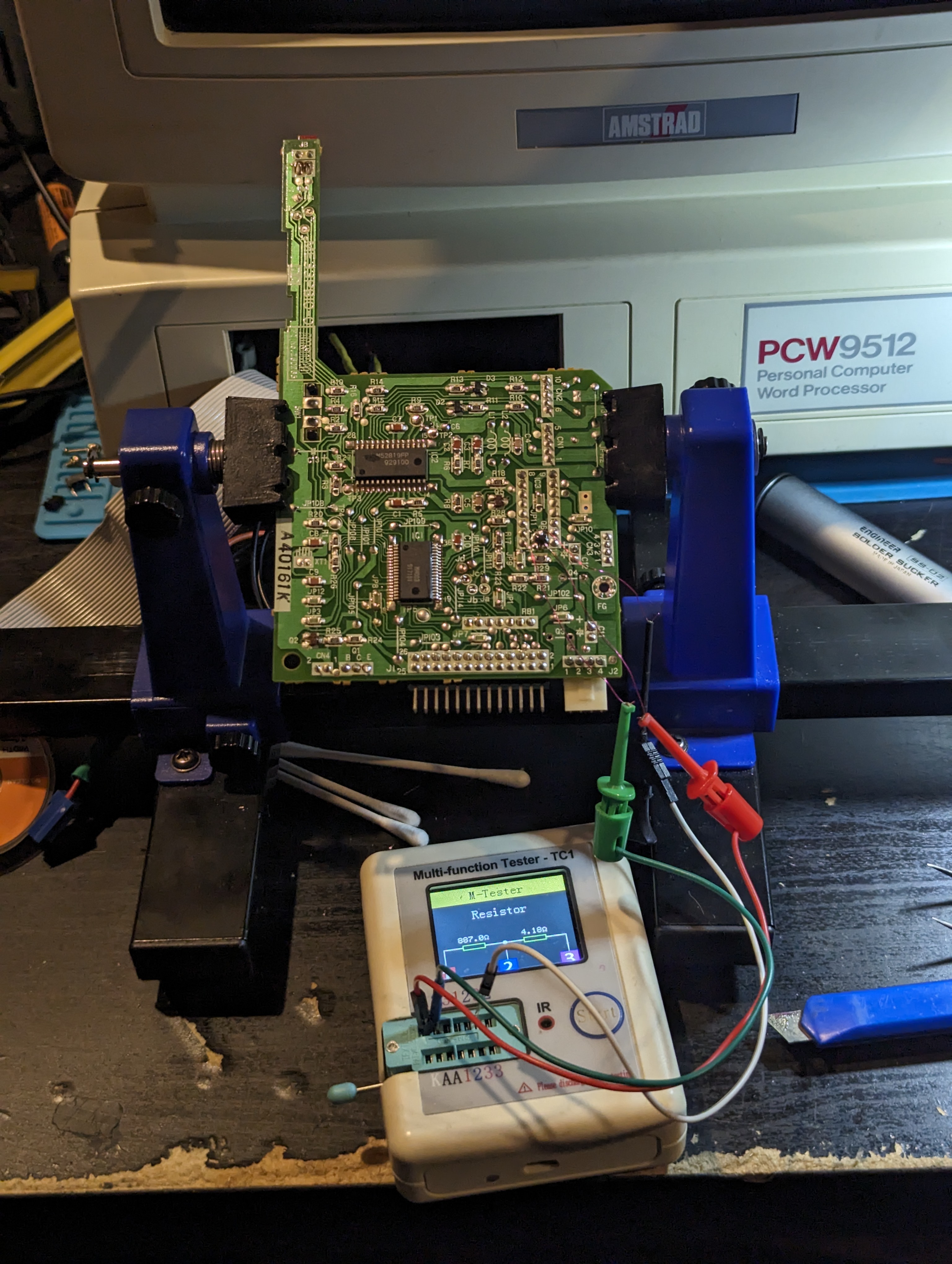 |
| Component tester plugs hanging from the thinnest wires in the world.. |
It came out as two resistors in series with values of 887 ohm and 4.18 ohm. This really doesn't seem right but could be as a result of the fact it is in circuit.
In the meantime, I have a cunning plan....for next time.
No comments:
Post a Comment