Sunday, January 28, 2018

Re-purposed Laptop Screen

Recently I posted on the Amiga Facebook group a picture of my A500+ setup (as below) which generated a few comments, specifically about the screen.

Real Hardware - no emulation here...
The screen in question is actually from a Compaq laptop that died several years ago. It was, allegedly, affected by a faulty GPU from nVidia, caused by crap soldering between the GPU chip and the circuit board. It was particularly widespread and even prompted a class action lawsuit in the US.

This laptop got thrown into a bag and forgotten until a couple of years ago. I wondered if I could use the screen somehow on my Raspberry Pi. To cut a long story short, yes, yes I can. It requires a couple of relatively inexpensive circuit boards and a bit of hacking at the screen but nothing too complicated.

The hardest bit was getting the screen out of the laptop which required totally dismantling the whole thing. When dismantling, there is a cable called the LVDS cable (I think) which is a bit delicate. It's the one the connects the LCD to the main board. Take extra care when removing it.

There are three main bits to the driver board I bought (remember that the screen has been removed wholesale from the laptop body).
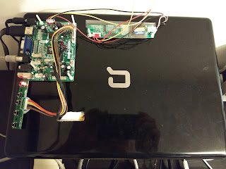
The Back of my professionally modified screen*
*Not professional(!)

First, there's the main board itself. The one I got hold of has VGA, HDMI and Composite inputs.

Main board - top view so you can see the model number
Main board - HDMI, VGA and composite inputs
Then, there's the control board which has several simple push buttons for the menu functions of the main controller board e.g. brightness, source input etc.

Control board
Finally, and most importantly, is the inverter board. This takes the low voltage from the board and inverts it to a level suitable to light the backlight in the LCD panel. This bit comes covered in thick insulating plastic for a reason. The voltage is high enough to make sure anyone touching it will have a bad day.

Inverter board - look but don't touch
With the board I acquired I also needed to acquire a power supply. This I got from a UK supplier who is subject to the strict regulations around electricity etc in this country. This is preferable to getting one from a supplier in China who isn't. It looks like a simple laptop replacement power supply and has a fairly standard 5mm barrel connector.

And that's basically it. I had to hack a hole in the back of the screen cover to get the backlight connector through and I drilled a few holes to mount the boards (blu-tack works fine for the control board).

DISCLAIMER - NONE OF THE INFORMATION BELOW IS INTENDED TO BE A RECOMMENDATION OR ENDORSEMENT OF ANY PRODUCT. I AM NOT RESPONSIBLE FOR YOUR ORDERS, ACTIONS OR YOU BLOWING UP YOUR CAT. THE INFORMATION IS PROVIDED IN GOOD FAITH AS AN INDICATOR OF WHAT I MANAGED TO DO. YOUR MILEAGE MAY VARY. SO THERE.

Sadly, I can't find the original listing on eBay that I bought this from as it was actually nearly two years ago when I did this (is it really that long?). They are still available in various forms though, just search for 'LCD Controller kit' and you'll see various results pop up.

A few points to note when ordering:

1) Remember to get one that includes the inverter board. Without it the backlight won't work.. I'd expect to pay around £25 (around $35 ish) for a complete kit.

2) Find out the make/model of the LCD panel you have before ordering. If in doubt, email the seller and ask if they support that particular model. Most LCDs have a white label on the back with this on (mine was an LG something or other).

3) Check what inputs are supported - mine does HDMI, VGA and composite which allows me to use my Amiga (composite), Raspberry Pi (HDMI) or even my work laptop (VGA). YMMV depending on which board you find.

3) Don't forget a suitable power supply!

Good luck.

Saturday, January 13, 2018

Voyager Model Build

A long time ago, in a galaxy far, far away...

No.

A long time ago, my wife bought me a model of Voyager from Star Trek. This has followed us through two house moves and two children (one now at University). I thought it was about time I actually made it.
Voyager - nice

Instead of the usual paint it, glue it, paint it, display it I though I would try and do a bit more. One thing that I always wanted to do was use lights inside one of this type of model beacause:

a) it looks cool
b) do I need another reason?

So, first things first. The windows. On this model they're all there but filled in. The larger windows should, in theory be three separate panels but, for this model, I won't worry too much about that as I have a 'workaround' that might work. Every window needs to be drilled out and sanded to shape.

I tell you what, there's a lot of windows on Voyager...

Windows started..

Windows on this side finished

After a few nights of drilling, trimming and sanding, all the windows had been cleared out.


Next thing, get some LEDs. In this case, eBay is my friend and I managed to get a batch of 50 super bright 3mm LEDs for about three quid. A bit of a wait for them to arrive from China but they're cheap and they work.

To see what affect they produce I hooked up three LEDs and powered them up inside one half of the main body of the ship. The result was, to say the least, disappointing. The lighting was very harsh and it was easy to see the LEDs. To get around this I took a sheet of thin plastic (similar to a laminating pouch) and sanded one side. Then I cut a couple of small pieces and stuck them to the inside with double sided tape. When the lights were switched on again I got a much more pleasing effect.

LEDs held on with Blu-tack

Exterior view

Another Exterior Shot

With all this I was well on the way. I need to make sure that there are no light leaks when I glue the thing together and I also need to plan where exactly through the whole ship I will be putting the LEDs. Even though I have 50, that's not as many as you'd think.

I also need to consider what current these LEDs will draw when they're switched on. Assuming that each LED takes 20mA and there are 50 of them then the supply needs to be at least 1amp (say 1.5 for safety). I also need to consider what heat might be generated inside. Somewhere, I have a spare 2A USB power supply for a mobile phone which might do the job and provides 5V. More thought on this is required...

Also, what I would like to add is:

a) Flashing navigation lights
b) Blue nacelle lights on the engines
c) Red ramscoop lights at the front of the nacelles
d) A light for the main deflector

More next time!