Monday, September 18, 2023

Anybody? No? Disk. Anybody? No? Disk. Anybody? No? Disk.

10 out of 10 if you get that reference..

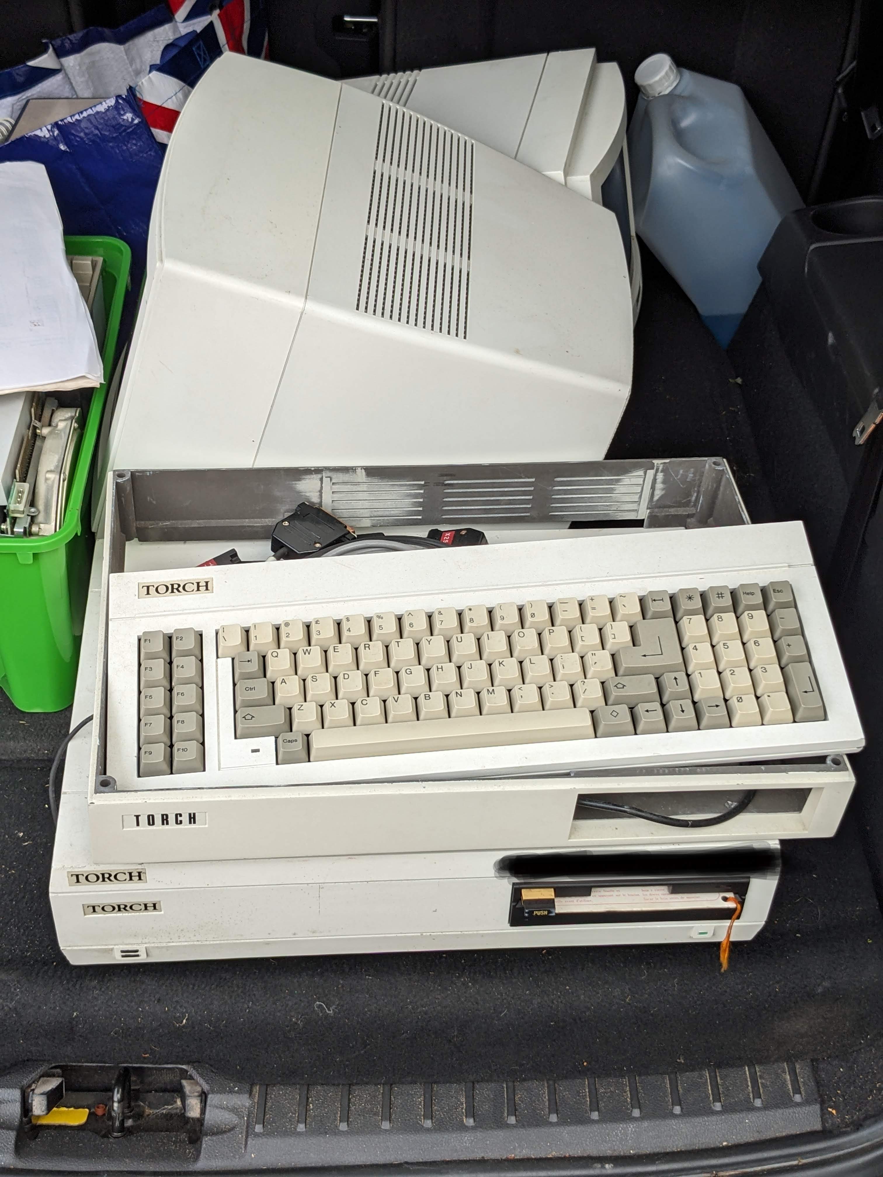
With the appearance of two rare machines in my garage i.e. the Cifer and (gasp) the Torch Triple X, I started to think about the media that came with them and what, if anything, I could do to preserve the software on them. 

Torch Triple X - Rare

Cifer 1887 - Also, a bit rare

Although I am a kid from the 70's I never owned a computer with a 5 1/4 inch floppy disk drive. I jumped from the ZX Spectrum+ to a SAM Coupe and then to an Amiga A500+. The Speccy used tapes and any floppy drives available for the speccy were way outside my 10 year old budget, costing more than the computer itself. Then the SAM used tapes or a 3.5 inch floppy drive and the Amiga also used the more modern 3.5 inch disks. So I had very little exposure to the delights of the greatest actual 'floppy' disk format.

Until now...

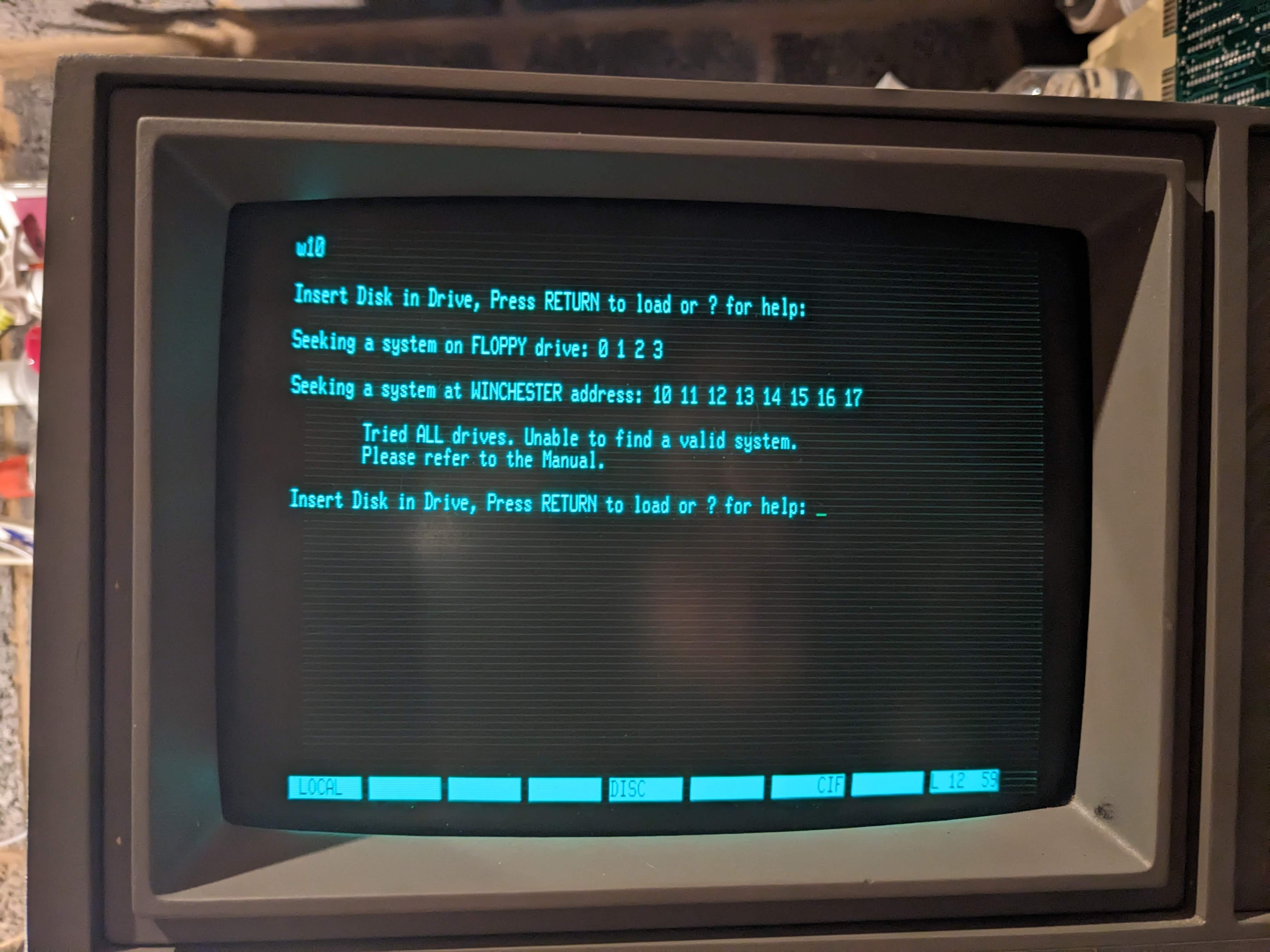
From having no 5 1/4 inch disks just over a year ago I now have boxes and boxes of them. A few are software for the Psion organisers, a big bunch are for the Cifer and the rest now for the Torch Triple X. All of these disks need to be preserved in some way, some more than others - for example the Torch has a 'key' disk that MUST be inserted the first time the machine is switched on or else it's just a large white box that does not very much. 

The first problem is that I don't have a PC with a 5 1/4 inch drive in it. I don't even have a working desktop PC that would accept one having long since succumbed to the portability of a laptop (even though my old HP is massive and weighs as much as a small child). The only physical drives I have are the twin drives in the Epson TF-15 unit, the drive in the Cifer and now the drive in the Torch. 

After some investigation I realised that I don't need a desktop PC to connect a drive to now that there is such a thing as a 'Greaseweazle'. This most excellent device with software by the ever awesome Keir Fraser is a small board that has a standard 34-pin connector and is powered by USB. More importantly it allows the contents of a disk to be captured regardless of its format (although common machine specific formats are supported natively too). This is achieved by the unit capturing a stream that comprises the variations in the magnetic flux on the disk surface itself. This can be saved into either RAW or SCP format for (in theory) writing to a new disk. Other formats can be written too.

It's worth noting that a floppy disk is basically a piece of plastic cut into a circle and coated in iron oxide that is somewhat the same as used in cassette tapes. Data is stored on the disk by magnetising small parts of the iron oxide in specific patterns. To read the disk back a read head simply converts the magnetic flux variations into electrical signals that are converted back into data. The Greaseweasle records this flux and puts it into a file for later use.

So the Greaseweazle I have is a V4 unit supplied by the excellent chaps at RetroPassion. The unit itself has a 34 pin connector, a four pin power connector and a USB type 'B' connector. There are also some jumpers that can be set, the most useful of which inhibits the units ability to write to a disk, providing some protection against idiots (who d'ya mean?) who might accidentally overwrite vitally important data...


It's not greasy and it's not a weasle...

I quickly 3D printed a case for it (find it here) and then set off to find a floppy drive. Because the unit uses a standard 34 pin connector this means that, in theory, any standard floppy drive will work including 3.5 inch drives, some 3 inch drives (may need an adaptor or the drives internal 5v disconnecting) and most 5 1/4 inch drives too. The first drive I found was a Chinon 'tall' 3.5 inch drive from an Amiga A500. 

After connecting it up I was disappointed to find that the drive did nothing, even with the power connected. After a quick search I found that some 3.5 drives use 12V which the GW cannot provide, requiring a separate power supply. The Chinon is one of them. Another quick scrabble in the garage produced a black PC unit that I had forgotten about. 

I wasn't sure what state this was in but I connected everything up and stuck in an Amiga disk - this is supposed to allow copying of disks agnostic of the system after all. :)

Mitsumi PC drive

Next question was what format to use. There are two main 'stream' formats. These are SCP and RAW. If using RAW you need to make sure you direct the output files to a folder and give them an appropriate name. The SCP format writes a single file so that's what I went for.

Initial results were disappointing. Using the HxC floppy emulator analysis tool the top layer was covered in orange and red and just didn't look right. After stripping the case off the drive I cleaned the heads and also realised that there was an adjustment slot on the spring holding the top head down. I moved it up to the highest setting and tried again.


Drive adjustment in progress...


Success! The stream created showed (almost) all green on the analysis tool in the excellent HxC floppy emulator software.


Then, using the HxC software, I converted the SCP stream into an Amiga ADF and successfully mounted it in WinUAE. Nice.

After this success it was time to move on to the 5 1/4 inch disks. As I had the Torch in pieces to try and repair the power supply I nabbed the floppy drive from that. Fortunately, the cable with this unit had the correct 34 pin connector for the Greaseweazle end. As I have a different laptop in the garage - a much smaller and slower HP that runs Linux I had to install the Greaseweazle software again as well as the HxC floppy emulator. Not quite as straightforward as the Windows installation but it all worked in the end.

First attempt at connecting everything up and the GW reported that it couldn't find an index. This normally means that it is looking for the wrong drive number. I changed the '--drive=' value in the command line to '1' from '0' and tried again but no luck. So I tried '2' and then jumped a mile as the drive clicked into life.


After reading in a disk image from a CPM system disk for the Cifer I was disappointed to see that the disk analyser showed large patches of red and orange as if the disk wasn't formatted or had errors. This was slightly disturbing but I persevered and tried to write the image to a blank disk and then analyse the pattern on the newly written disk. It did not go well.

CPM disk for the Cifer read using the Torch floppy
Something ain't right..


The scp stream written to a blank floppy and read back in
Definitely not right..


Hmmm. I started to think that this must be the drive at fault so, after some deliberation and a lot of moving stuff around I took the drive out of the Cifer and tried again. This time the results were startlingly better. Every track was green, dark green for data and light green for formatted but empty with only a couple of orange/red spots. Awesome!

That's more like it...


So, what is wrong with the Torch drive? I'll give you one guess. 

Yep.

Capacitors.

There are a few electrolytic caps on the control board of this drive and some of them have leaked. A video here from the most excellent Mike, showed that his drive of the same model was doing exactly the same as mine before being re-capped i.e. with a clicky bouncy arm thing. And, for the second time, replacing the caps fixed the issue (or to be honest, a partial re-cap as I didn't have all the values but it was enough.)

Torch floppy drive after (partial) recap

So, now can this drive read disk streams as well as the Cifer drive? 

It works!


Oh yes.

So, now I can capture disk images, regardless of format, can I write them to a blank disk and get them to work in the Cifer? Well, sort of. For some reason, just copying the scp stream back on to a disk always gives an error when the Cifer tries to boot.


Track 2, sector 9 every time... very odd.


Looking at the flux representation showed a strange fuzziness on the written disk compared to the original and I still don't know why. More bizarrely, this fuzziness appears if I use the Cifer drive to do the reading/writing too. 

Left box shows original, right box shows written disk with 'wiggle'


This could be down to my only being able to do a partial re-cap on the drive resulting in a reduced bouncy arm thing for reading (it's a 'head load' arm to be precise) but still slightly bouncy for writing. I will see about ordering the rest of the caps.

For now, I worked out that I could go via an intermediate format, in this case .IMD which is a format associated with a PC utility called 'Image Disk'. This is apparently a very useful and powerful tool but it requires a PC with 5 1/4 drives etc which I don't have. But the HxC software does write this format, as does the greaseweazle tools I think. In any case, after writing an IMD file of the CPM disk to a blank floppy I stuck it in the Cifer and booted it. 

And it worked! Yay!

Cifer booting! YES!

So, just one last thing. That 'Key' disk for the Torch. Can I read that too? You betcha!

Torch Key Disk Image - backed up and saved. Phew!


Back to the Torch next time.


Monday, September 11, 2023

A Torch - well every adventure game needs one of those, doesn't it? - Torch Triple X Part 1

Not that sort of torch. This is a Torch computer. Specifically a Torch Triple X (I say!). Released in 1986 this was a UNIX workstation based on a 68010 CPU with floppy disk, hard disk, UNIX SysV and a colour GUI with a mouse. This might seem rather advanced for 1986 but, to be fair, the Amiga was a contemporary being released in July 1985 and that had a similar, if rather more orange and blue, OS and a rather uncomfortable mouse.


It's a Torch. With two monitors.
Nice.


This particular Torch Triple XXX (which I shall refer to as the T3X to save my middle aged typing fingers) was once used as part of a command and control system and was last switched on sometime in the 1990s. As a project, this is going to be a rather long term thing. There are several slightly odd things about this machine that have to be sorted before any electrons from the mains supply go near it. 


Under the hood. Floppy to the left, winchester in the middle
and power supply on the right.


Under the hood 2 - The main board but note the 'Limpet 
Board' on the right giving an extra 1mb of RAM

First up, the power supply. It has a battery. Which has leaked. It also is essential for the correct operation of the system as it uses an innovative (for the time) capacitive 'on/off' button that would rely on the capacitance of a finger to switch the machine on. If the machine was on and the button was pressed, it automatically shut the system down gracefully. Innovative? Maybe. A pain in the arse over 35 years later? Yes, yes it is, but I'm getting ahead of myself.

Second, the hard disk. It uses a small winchester disk and, if you're a regular reader, you'll know that I don't have a lot of luck with ancient hard disks. The Mac Classic II and the Cifer spring to mind.. Fortunately, I have a full set of SystemV floppy disks in a box. Which leads me nicely on to..

..The 'key disk'. This is a floppy disk that MUST be inserted when the system is factory reset. Without it, the unit is a nice heavy doorstop. When it's been inserted once, the battery in the power supply (remember that?) keeps the information stored so you don't need to use it again. Until the machine is reset. Or the battery dies. Or it goes into storage for twenty years before landing in my garage.

Let's take a proper look at the power supply first. It looks fairly standard but when I took it out it was obvious that some moisture of some sort had got in to it. At this point I hadn't realised that there was a battery, but this innocence was soon lost when I realised why the damage I was seeing looked startlingly familiar... 


Battery damage. :(

White barrel battery. I sentence you to be removed...


Quick aside. There's a freakin' huge RIFA in there with a dirty great crack down it. Magic smoke has already leaked out clearly.


Smokin'...


The battery damage is extensive on the bottom of the board. I scraped away the solder mask on the tracks that were affected. Then I carefully re-flowed all the joints that had become dull and grey. This wasn't straightforward as the battery chemicals react with the solder joints to create a grey, crystalline blob that doesn't really melt very well. I had to take my soldering iron and copious amounts of flux. Heating each joint I could see when the solder under the gunk started to melt and then used the solder sucker to get rid of the worst.


Repairs in progress.


Despite my best efforts, there are at least four pads that have disappeared or broken. One track has basically been eaten away to nothing and will need a chunky bodge wire to repair.


Track eaten away by battery leak.


On the other side, there were several component casualties too, although they were all resistors. Seven in total basically fell of the board due to the corrosion of their leads from the leaky battery. These should be easy to source and replace though. No other components seem to have been affected as badly. A simple scrape and clean up of the diodes, transistors and capacitor legs seems to have done the trick.


Casualties of (battery) war..


And that's about it for part one of this project. I need to order some new resistors (don't feel happy using the uber-cheap skinny bits I bought from a man who claimed to be in the UK but was clearly located somewhere in China) and, of course, a replacement for the RIFA smoke generator.

More soon..


Monday, June 05, 2023

Fake it til you..err..fix it.

After another frustrating couple of days with the Cifer I decided to take a small step back and try and sort a couple of smaller projects out. 

A while ago, I was given a 'Fakerscope' which is a handy device for intercepting and decoding RS232 communications. It actually does much more than that but that's for another post. It worked fine for a while and helped me out a bit with the Oval serial display adaptor (although I eventually did RTFM).

But all of a sudden, the display stopped working. It was blank, and no amount of fiddling or switching on or off would solve it.

It's worse than that, he's dead, Jim.


So I took it apart and found that, even though the battery had been removed by the previous owner, the capacitors on the display had some corrosion and, as it turned out, several of them had leaked too. At the time I didn't have any 10uf 50v caps so I ordered some and put the pieces of the 'scope away. And there they stayed for about eight months.

So tonight I fished out all the parts and screws, and dug out the long since received caps. 

Bag 'o bits.


I'd removed the caps but some corrosion was still on the pads so it took a few minutes to get them into a state where they were nice and shiny. The fishy smell from the pads confirmed the leaky cap theory. Six caps were duly replaced.

Note the artistic folding of legs on the radial caps. :)

Putting everything back together was a bit more involved than I thought. I'd managed to lose some of the plastic spacers on the screws that held the screen to the top of the case. And I'd forgotten that some of the screws were horrendously tight and the heads had been damaged when I removed them. And I realised I'd lost the screws for case.. I really done gone messed up on this one chief.

Hunting through my spare screw box, I managed to get enough screws the right length and pitch so I thought I was ready to go.

But.

After connecting everything together the display didn't work. Then it started to make clicking noises. Hmm. Best switch that off...

One tiny detail I'd forgotten; the cable that connects the display has a red line on pin 1. Except it isn't. Yes, the cable is, to any sane person, the wrong way around. From factory. Which I forgot. Doh.

Fortunately, no damage was done and as soon as I switched the cable, it sprang back into life. Yay!

Nice, proper display. Nice.


So, this was a rare case where changing the caps DID repair the fault. Yay!

Wednesday, May 17, 2023

What's the frequency, Kenneth?

The Cifer is proving to be an interesting project. I've never worked on a computer that had soooo many discrete logic chips. As identified here I managed to find some that were dead across all of the boards in the machine. Today, I shall be focussing on the graphics board.

This board had the following broken chips:
  • 74LS166 at ML9
  • 74LS163 at ML37
  • 74LS163 at ML38
  • 7425 at ML45

Graphics board - I don't think NVidia will be too concerned..

All of these broken chips were replaced, but before we get to the board, a slight detour.

Across all the boards I noticed that every 74LS166 and 74LS01 came out as faulty on my chip tester. This did make me wonder but I ordered some new ones of each variety anyway. The first to arrive were the 74LS01s and these were brand new old stock. Every one came out as 'bad' on the tester. Hmmm. 

Bad chip!

When the 74LS166s arrived I checked them too. Every one came out as 'bad' on the tester. Double hmmm. Then, second batches of both chips arrived, and every one came out as 'bad' on the tester. 

Bad chip?

So, a word of caution. If you have a chip tester labelled TES-200 then take what it says about 74LS01s and 74LS166s with a pinch of salt. 

Incidentally, you may have noticed that I 3D printed something to bolt the tester to. This was because the display was way too wobbly and I couldn't plug the battery in without the display pushing up out of the socket slightly. 

Desoldered headers

Desolder pins

Sophisticated and delicate fixings.
OK, so I used a glue gun. Don't judge me.


So I de-soldered the pins and socket and wired the screen to the board and bolted it all into a 3D printed box thing. It's rough and ready but it works and it's far easier to use now.


And now, back to our regular scheduled broadcast.

The graphics card in the Cifer offers Tektronix 4010 emulation. This graphics standard actually used a 'storage tube' for its display. This is a type of CRT that retains the trace of the electron beam on the display, which meant that the computers that used it did not require additional display memory to store the image on screen. Think electronic etch-a-sketch. Here's a youTube video showing a display in action.

Obviously, the display in the Cifer is a standard CRT so this mode is, apparently, more about emulating the commands of the display than the look and feel of the display. No matter, it needs fixing so fix it we shall.

To get to the 4010 mode there are a couple of key presses required. First, I have to press F6. Then to enter graphics mode, I press the (can you guess?) 'Graphics' key. What should happen is that cursor should change to a triangle, and text should appear when keys are pressed in the same way as in standard text mode, but the text is generated from graphics card instead.

What actually happens, is that the cursor sometime changes to a stretched out triangle, sometimes it disappears. When keys are pressed, they occasionally get displayed but are very tall and spaced out. Also, random garbage frequently appears, almost like there is a RAM fault, even though the RAM has been checked several times.

One other detail is that, when the board is plugged in there is a high speed 'chirping' noise from the machine. This noise is only present when the little plug in connector PL1 on the board is connected. The other two connectors (PL2 and PL3) are for the serial comms to the main board and the IEEE488 bus respectively. So, it was over to the technical manual and the schematics to see if I could work out what was happening.

One page of several of schematics


First thing I discovered was that it looks like the IEEE488 chips are pointless as they don't do anything for the graphics board. Possibly a 'future improvement' that never got implemented.

So, why is the board chirping and displaying garbage? I started at 'VIDOUT' and worked my way backwards into the board. I checked TR1, TR2 and TR3 and they all matched the expected values. Eventually I ended up at TR5. This also checked out OK but I noticed on the schematic a variable capacitor. I wonder if the technical manual mentioned this? It did.... It is the control for the overall frequency of the video signal. 

Reaching for a small flathead screwdriver I switched the Cifer on and listened to the chirping. Then I started to gently twist the variable capacitor. The frequency of the chirp changed and the garbage on screen also changed, pulsing more or less rapidly depending on which way I twisted the screwdriver. After a few seconds I hit a sweet spot and the chirping stopped and the garbage on screen became a stable picture - still garbage, but stable. 

Variable Cap

Casting caution to the wind I pressed the reset button. Still no chirping. OK. Press F6 and then press 'Graphics'. The cursor changed to a nice solid flashing triangle. I pressed a few keys. They ALL worked. I pressed Ctrl+Disc. The usual '...Is the IEEE cable connected?' message appeared but in the graphics font. OH. YES.

This graphics board is fixed. 

Tektronix emulation in action. Nice.


Sunday, April 16, 2023

Testing, Testing. Is This Thing On?

So, after a bit of head scratching at the Cifer and the lack of IEEE488 bus, I opened my wallet (cue jokes about moths being released, we've been decimalised since the last time that was open etc etc) and bought a cheapo IC tester labelled as a TES200. It has the capability of testing many of the 74xx and 4xxx series of logic chips. It doesn't do them all but there's so much discrete logic on the boards there is a good chance I will be able to find some broken chips.

(But before it arrived I managed to check all of the Z80 processors, courtesy of my trusty ZX Spectrum, as well as the ceramic 68000 processor on the 68K board in a handy Amiga A500 motherboard.)

And then the tester arrived and it was good. Break out the chip removal apparatus!

TES200 on the right.


First up, the Display Processor. This is the first board in the system (or actually the last one when  disassembling it) and is the one with loads of EPROMs on it. There are several chips I can't test as they aren't supported by the tester (74LS244s, 74LS245s as well as the RS232 drivers 1488 and 1489s) but there's plenty to go at.


So many EPROMs...

And here's the list of broken chips the tester identified on this board (the 'ML' ref is just the component number on the board):

  • 74LS163 at ML75
  • 74LS01 at ML67
  • 74LS166 at ML64
  • 74LS166 at ML66


Next up, the Disc Processor board. This is the board that controls the floppy drive via the FDC chip and is the first on the IEE488 bus.

Disc processor board, for..er...processing discs..

Broken chips on this board:

  • 74LS01 at ML40
  • 74LS01 at ML45
  • 74LS08 at ML51
  • 74LS139 at ML83


Now for the Graphics board. This provides emulation of the Tektronix 4010 graphics standard (think about the computer line graphics used in the original TV series of Hitchhiker's Guide to the Galaxy - although that was actually a bit of a cheat as they were made with traditional drawn animation). The graphics mode has never worked so I was expecting some faulty chips. I wasn't disappointed..

64kb of RAM - not exactly an RTX 4080...

Broken chips on the Graphics board:

  • 74LS166 at ML9
  • 74LS163 at ML37
  • 74LS163 at ML38
  • 7425 at ML45


Finally, the 'big daddy' board. The 68000 user processor board. Now, I have tested the RAM on this board and some of it appears to be a bit flaky. So I should still be able to use half of it if I can work out where those 16 DRAM should go in the board. Also, there are two LEDs on the board that are permanently lit when the board is installed and I don't think they should be i.e. they're there to indicate a problem. And, lastly, there are two logic chips at the bottom of the CPU that get FREAKIN' HOT when the board is installed. So, what shall we find?

Gorgeous ceramic MC68000. Nice.

Broken chips on the MC68000 board:

  • 74LS166 at ML5
  • 74LS166 at ML10
  • 74LS158 at ML17

Now, 74LS166s are shift registers and I suspect that with the two shift register chips being dead, this board is not going to do very much.

Anyway, following the release of more moths, replacement chips were ordered and are now 'on the way'. Once they arrive, the fun shall re-commence...


Saturday, March 04, 2023

The Wheels On The Bus Go...

 ..."Cannot try Winchester disks as IEEE bus is not active. Is the IEEE cable connected?"

Stop mocking me...

Dangnabit. After getting so far with the Cifer, I hit a brick wall. The hard disk on this computer is connected via the IEEE-488 bus that permeates the entire unit. Basically, there is a 488 connection from the desktop processor board which then links out to the graphics board, the MC68000 processor board and the SASI controller board. SASI is basically the first version of SCSI. See the most excellent video from RetroBytes for more SCSI history.


Desktop processor board, for processing err...desktops?

The Cifer SASI controller board is really more of an interpreter, since there is a 'real' hard disk controller connected the drive, a Xebec 1410. This then feeds the SASI (see later on) data into the SASI interpreter which then translates it into IEEE-488 data and fires it across the bus.

At least, that's the theory.


Don't get SASI with me young man!

A week or so ago I decided to look more closely at the hard disks. I was disappointed that they didn't seem to work, although it should not be unexpected given their age. I had decided to follow the example of Adrian of Adrian's Digital Basement to see if the head stepper motors could be coaxed into life (see here and here).

To do this, I plugged the drive into power and switched it on. Just before the drive would lock the head stepper motor I quickly turned the knurled knob (no sniggering at the back) and watched to see the result. Interestingly, on both drives I had the same result. A fairly rapid resetting of the head back to a home position. But also, once I had done it a couple of times, it became obvious that the drive heads would, when left alone, do a very small but perceptible 'shuffle' once the drive reached full speed. And it did the same on both.

Incidentally, as part of my fiddling with the units I stripped them down a bit to get all the dust and cobwebs out (foreshadowing). 


The bottom of the drive spindle with brake.
 Splendid.

The Rodime drive board. Lovely.

The other en....ARGHAGAH!!!

As a grown man, I should not be able to make such a high pitched squeal of fright. The vacuum cleaner was summoned..

Anyway, after this slight detour, I went back to the unit and decided to do some chip swapping to see if I could prompt the bus to start working. It did not go well. There are several Z80 processors scattered around this machine so I thought I'd start there with my swapping. Removing chips is normally no big deal. Except when it isn't.


There's still 39 legs. What's the problem?

Unexpected socket replacement in 
the workshop area...


Fortunately, it was fairly easy to repair by soldering an offcut of a component leg to the remaining portion of the original leg that was left. With a new socket installed I put everything back together (or had I?) and tried again.

One step forward...

But then I realised I hadn't plugged the power back into the SASI board. Which I then rectified and plugged power in.

...Two steps back.


AAARGHHH!!!!

(To be continued....)