Wednesday, March 23, 2022

This Time It's Serious - Hung Chang HC-5504 Oscilloscope Repair

Parts have started to arrive for the planned repair of my oscilloscope. I will document what I do here, and try and do it properly so anyone who has the same problems or needs to replace the HV tripler in this type of oscilloscope might stand a chance, based on my success (or failure) to do the same. Some information here is duplicated from previous posts.

The oscilloscope in question is badged as an IsoTech ISR441 40Mhz scope. I believe that these were branded by RS Components in the late 80's and early 90's. Following the research and lucky finds I had on the internet I can identify that the model I have is a re-badged 'Hung Chang' 5504 40Mhz oscilloscope. The link to the manual can be found here from the EEVBlog forums. (If this stops working leave a comment and I'll see if I can fix it.)


Hung Chang 5504 40Mhz scope

The problem I had with the scope is basically it now has no trace. Prior to the trace disappearing I had noticed that it had started to become dim, but only sometimes. Once it was dim it would sometimes go back to being bright again, sometimes it would not. Changing the controls had no real affect that I can speak of. One day, the trace was bright as normal, and the scope was on. After a few minutes I turned to use it and the trace had disappeared.


Switched on but no trace


Checks revealed that the test signal on the front still works and power supply rails are at the correct voltages.

Inspection of the board with the HV circuit (there are two main boards in the scope - the one in question is the board mounted on the side of the scope) revealed that there were apparent burn marks on the HV tripler unit at the point where the Anode cable leaves the unit. There were also signs that the plastic case had started to melt and had expanded and 'bubbled up' in some places. 


Burn marks close to Anode cable

Deformed plastic case

Removal of the HV tripler from the circuit board also revealed a large hole in the plastic with evidence of the expulsion of burnt potting compound onto the heatsink of a nearby power transistor (Q2001).


Hole in faulty tripler

Q2001 heatsink shows the material expelled
from the faulty tripler


This scope makes use of a separate Flyback Transformer and HV Tripler unit rather than the more conventional combined units as seen in CRT TVs and CRT based computers such as the iMac G3. 

Page 37 of the manual shows the circuit diagram for the voltage tripler unit. These units are not manufactured and so the only option to repair this scope is to build a new tripler from discrete components using the parts list and circuit diagram as a guide.


Tripler circuit diagram (page 37 of manual)

The components required are:

  • 6 x 1000pf 6kV ceramic capacitors
  • 6 x Y-16GA or equivalent 10kV high voltage diode (typical forward current 5mA)
  • 1 x 1/2W 10M ohm solid resistor
The components I have purchased are:
  • 6 x 1000pf 15kV ceramic capacitors
  • 10 x 10kV diodes
  • 2 x 1W 10M ohm resistors

Note that the ratings I have may differ from the service manual. This is primarily due to availability of components, especially the capacitors. Note that in most cases it is acceptable to pick a voltage rating higher than the original component. 


Capacitors and 1W resistors


I will also be making use of the original Anode cap and cable. To contain the unit, once constructed, I have 3D printed a small box that matches as closely as possible the dimensions of the original ABS box. This initial 3D print is made with PLA which, despite being an excellent insulator at room temperature, begins to lose its insulating properties as its temperature rises towards 65 degrees celsius. As such, I would not recommend PLA for the final box since it sits very close to the heatsink for the large power transistor Q2001 - a D880. Using ABS instead of PLA will provide a more suitable box since ABS has a much higher 'glass transition' temperature i.e. the temperature at which the plastic starts to become 'rubbery'.

In my case the PLA box will be used to evaluate whether the constructed tripler fixes the oscilloscope and, if so, a more appropriate container will be procured/constructed/printed.


Two sizes of replacement box

Q2001 and Heatsink
(Note proximity of tripler box outline)


Space is very limited within the confines of the board and the fly-back arrangement is also covered by a silicone (or rubber) lined aluminium cover. I intend to use the space as the factory unit did with the 3D printed box, if possible but it will be tight due to the number of components required to build the unit. If the aluminium cover is to be retained, which I very much hope I can do, the potential for going beyond the original unit size is very limited due to the mountings of the two main boards.


Aluminium cover - limited access

Tripler Construction

To start, I laid out the components that I have in a rough pattern of where they would sit. Note that in this picture I was still waiting for the final delivery of diodes to complete construction. As such, the final diode is missing from this picture which would connect from the top right most diode to the resistor and capacitor bottom right.


Rough Layout

First, I soldered the two groups of three capacitors together, making sure to leave a small amount of leads between the caps so that I had something to connect the diodes to. Then I twisted alternate ends of the diodes together to make an extended 'W' shape, being sure to put the cathode (the end with the markings) pointing in the correct direction. Following the circuit diagram, with voltage coming in from the left, the cathode marking was on the 'right' of every diode following through the ladder.

Once this was done I soldered the legs of the diodes to the gaps between the caps. This resulted in the following:

Partially constructed

Due to the limited space in the box, I put the caps so that they will be at the bottom of the box with the diodes connected on top. There is also a 10M ohm resistor that is the final component before the cable that runs to the anode cap at the CRT.

Resistor added to end of Anode cable

The leads of the first two caps are long enough to extend down through the bottom of the box and into the correct places on the circuit board i.e. the two holes at the 'In' end of the tripler outline. The two holes at the 'Out' end of the tripled are only used for anchor points (an assumption) as they both appear on the ground plane underneath and the actual 'out' voltage is the anode wire and cap. 


Tripler location next to transformer
Note 'In' and 'Out' markings

I intend to to use a 'u' shaped piece of silver wire to perform the same anchor function in the 3D printed box I will use. In the picture above the space for the tripler has two holes on the left which are the ground 'anchor' points, and two holes on the right. The hole nearest to the transformer (top) is also ground. The hole at the bottom is the 'in' voltage that arrives from one side of the flyback transformer.


Completed construction
(note second diode has become disconnected)

Following completion of the tripler, I installed a small piece of silver wire to support the box at the end where both connections connection to ground. Next, I placed small pieces of heat-shrink on the joints of the capacitors to try and reduce the potential for arcing between the components due to the high voltage. Then I slid a large piece of heatshrink over the end of the anode cable before soldering the end of it to the final diode/cap joint in the ladder.

With this done I slid the whole thing into the box, lining up the two legs of the first section of the ladder with two holes I made in the bottom of the box. These holes line up with the 'in' and 'ground' connections on the 'in' side of the tripler. Finally, I put a piece of insulating tape over the top to hold the cable in.

I have some concerns with this very temporary design. First, I don't know if my efforts to insulate the components have gone far enough. Ideally, the whole thing should be potted into the box. BUT, as mentioned above the temporary box here is made of PLA and is not ideal for scenarios with temperatures over 65 degrees celsius and so it will be replaced. Potting it would make box replacement almost impossible without re-building it all over again. Second, the final 10M ohm resistor presses up against the PLA. I don't know how hot it may get and so I am wary of leaving it in there since, if it gets too warm it may melt the PLA exposing the resistor to potential arcing targets.

So, this arrangement (as shown below) will at least show if this is going to work.

Assembly complete
Ready for installation

Re-installed on the board.

Awaiting main unit re-assembly

Re-assembly of the oscilloscope was a reverse of disassembly. There were three wires to re-solder into board, one brown wire (connects to a BNC connector on the front panel) and the two wires that drive the CRT 'x' deflection. I had to be careful soldering these back in as the pads on the board started to lift when I removed the cables originally.

All the screws were re-installed and the plastic cover re-attached with the black pegs holding it in place. The cover is important as it offers some protection against accidentally touching the high voltage section of the board - so not to be left off! The numerous connectors were re-attached with their positions being fairly obvious due to the orientation and natural position of the various plugs, so there were no issues there. A couple of them are deep inside the centre of the board and I found a long pair of tweezers were helpful in getting these re-connected.

The main power cables were re-connected to the board and these were the only connections I hesitated on as I realised I did not have a good photograph of them pre-disassembly. I verified that I had them correct by checking the connector orientation and voltages in the manual. 

Re-attaching the CRT neck board was straightforward as the connector is keyed and will only sit flush if attached correctly. Finally, the anode cap was re-attached to the CRT.

This is now in a suitable condition to try a switch on. 

Ready for test run


To ensure maximum safety I plugged the unit into an extension cable and then took it and placed outside of the garage door. The thinking being that in the event of a catastrophic failure the damage would be limited to my garden and not the garage and its contents. In addition, I took the added precaution of using a piece of wood to turn on the main power switch. 


And the result was... a working oscilloscope. This is a fantastic result but not the end of this project. As mentioned above I intend to 3D print an ABS box which will be far more heat resistant that the PLA one currently installed. Once that is done, which will require another disassembly and re-assembly, then I will move on to the calibration process which, thankfully, is well documented in the manual.


Success!


Wednesday, March 09, 2022

Sillyscope Second Shenanigan Sure Sees Satisfaction Swell

After a Twitter poll in which a grand total of three followers voted (still not as bad as the turnout at the local elections) it was decided I will attempt to repair my faulty oscilloscope. This requires the building of a new HV unit known as a 'tripler' and makes use of diodes and capacitors in a 'Cockroft - Walton' configuration. This will replace the sad, burnt out remains of the previous unit...

Burn marks aplenty

In a nutshell, this 'ladder' of components takes the voltage at one end (say 2000V) and multiplies it up to a much higher voltage (6000V if the input is 2000V). So, not something to be flippant about since high voltage can kill. 

While researching how best to approach this I came across a reference to a type 5502 oscilloscope - what I did was try searching for the reference that is on the top of the flyback transformer - and as luck would have it, the manual was available as a badly scanned, low resolution PDF file. A quick look confirmed that this was almost the same as my oscilloscope, but this model in the manual was a 20Mhz version, whereas mine is a 40Mhz version. 

Closer inspection revealed that there were some significant differences. Most annoyingly, these were centred on the HV section of the main board where it appeared as if there was no potted HV marked tripler, rather just a bunch of diodes and capacitors. Whilst not a disaster, this did make me wonder if the values for those components in the manual would actually match my unit.

Then I had a brainwave. The model in this manual was the 5502, which is a the 20Mhz version. I wondered if the 5504 would have been the model number of the 40Mhz version. Google is my friend. Indeed, it is my friend forever now because searching for '5504 oscilloscope' lead me to a webpage that had a link to a manual. But was it the right one?

My Scope

Is it a match?

OH YES! Not only is this the correct manual but it also includes a list of components and a schematic for the HV tripler (which is actually a 'Three Stage Half Wave High Voltage Multiplier') which means I know what parts I need to order! That is, I believe, a bit of a result.

There are huge advantages to having the manual for this thing. Firstly, it gives me the correct specification for the parts for the HV unit. Second, it also provides a method of calibrating the scope on the assumption that replacing the HV unit is probably going to send it slightly off calibration. Finally, having the full instructions means I can make sure I am actually using this thing properly - assuming I can get it working again..

So, what parts do I need? Here's the bit of the schematic that's important:


Danger! Danger! High Voltage!

So I need six high voltage diodes (10kV), six high voltage capacitors (1000pf, 10kV). Values are shown in the helpful list of components:

Certainly the oddest shopping list..

I have already ordered some diodes but I actually need to order a few more. There were five in a pack and I ordered them before I found the manual thinking I'd only need three (for a doubler) or five (for a tripler) - in actual fact, I would've always needed four or six but I did not spot that until too late... No worries.

The capacitors are about to be on order when I can find someone with the right values and can deliver sometime in the next week or so. In fact, I just found someone selling 1000pf 15kV caps. They'll do.

With a fair wind and the avoidance of World War 3, I should have all the parts by next Saturday (19th March). 

I shall be building a voltage multiplier to take 2000V and boost it to 12000V.

What could possibly go wrong? 


via GIPHY

Saturday, March 05, 2022

A Sillyscope


Video Signal - Single Field

A little while ago my most excellent boss gave me his old oscilloscope. It's an Iso-Tech ISR440 which, from the limited information I have managed to find, is a brand from RS Components in the UK and it was made circa 1990(ish). So it's a good few years old but the display was nice and bright and it's just what I needed to replace the self-built kit (which is surprisingly good for its size), and the scope-meter donated by my other most excellent boss, but which has a problem of the screen contrasting decreasing all on its own... Some pictures of happier times.


Video Signal - Two Fields

RAM Access


Recently, during use, I noticed that the trace suddenly seemed to be very dim so I did what every good engineer might do. I turned the brightness up. After a few more days I realised that the trace was very, very dim and the brightness needed to be at full tilt to see the trace.

Hmmm. A problem may be developing...

Another few days went by and I had the scope on and it was working but then, all of a sudden, it wasn't. The power light was on but there was definitely nobody home. 


Nooooooooo!


After some attempted percussive maintenance (a couple of sharp taps on the top and sides) I realised that it was dead. 

Those of you out there who know anything about CRTs, be they in TVs or oscilloscopes will know that they need large voltages to work correctly, typically anywhere from 6000V(6kV) to 18000V (18kV) depending on tube size and application. I had initially decided not to bother as I don't want my face burned off, and to put it down to experience. The scope is 30ish years old after all. But then I had a change of heart after watching a few youtube videos on scopes with no trace. Several seemed to indicate that a simple capacitor failure related to the drive circuit was enough to prevent a trace from appearing. If I can fix this with a simple cap replacement, that would be awesome!

Initial Testing

Normally, anyone trying this would need a schematic but this model has no documentation available online at all. There are a couple of mentions of it in RS Components notices of obsolete equipment but no manuals, no schematics, nothing. This makes things more difficult but not impossible.

The 'calibration' signal on the front of the scope still works. I can get a clear square wave at the right voltage which I can view on my 'kit' scope. So that indicates that there's a good chance that the power supply is OK.

Next, time to get down and dirty inside..

Show us your bottom

And here's the top

I found the main transformer where the power enters and tested the voltages at the point where they joined the PCB. They didn't really match what I expected but I suspect I was measuring them incorrectly. A quick poke around the board showed that the following DC voltage lines were present:

  • 3.3v
  • 5v
  • 12v
  • -12v
  • 148v

I have to assume that these are OK as they look within the ranges expected in this type of equipment and, of course, I don't have a schematic..

Incoming mains transformer

Bottom row of connections is the main power in

Next thing. Assuming that there is power going in OK, what about the tube? Is voltage reaching the heaters in the CRT? After nervously switching it on with no covers on, the answer was proved to be, yes. A gentle glow was emanating at the end of the CRT where the control wires connect.

It's small but it's there

Closer, closer, closer...

Voltage is reaching the end of the CRT then. Next, there are a couple of neon lights on the main board which are used to reduce the voltage on the grids inside the CRT (massively oversimplified and possibly wrong explanation there). In any case, the neon bulbs remain off at all times. They should flicker slightly as the power is switched on or off but no response, Captain.

So now it's time to get that HV board out. As the scope is sat in its regular position the board is located on the right side of the unit or on the bottom if the scope is stood on its end. But before I go anywhere near it with a screwdriver though, I have to discharge the CRT. This is a well known, straightforward and terrifying procedure which involves attaching a cable to the frame of the scope (with a crocodile clip) then to a screwdriver (also crocodile clip) and then sliding the screwdriver under the Anode cap, ensuring that contact is made with the metal clips on the cap. 

There be dragons...

Pah. What's the big deal?

I found out a few things while doing this. Firstly, the Anode cap is not as tight as the ones on other CRTs I've discharged (mostly old Macs) and this one popped out a little quicker than I thought. Second, it looked like there was no high voltage on the cap or the tube as there was no crack when I made contact with the metal contacts on the cap and the tube itself. Finally, I really hate CRTs.

Anyway. With that done I could now get on with the process of dismantling this thing. The next item was to disconnect the voltage connector at the back of the CRT. I knew I'd have to do this as some of the wires on the HV board linked directly to the connector and were already quite tight. This was easily done although I was very gentle as I did not want to break the neck of the CRT. That would be bad.

Neck board removed

And now, to remove what felt like 100 screws and earth wires (actually more like 12 or 14 or so) and disconnect a billion connectors (more like 10 or 12 or so). I also had to remove the knobs on the timebase switch as this is mounted directly to the HV board. They were held on with a couple of grub screws that needed a tiny allen key. Fortunately my multi-screwdriver bit set had just the right size and they were removed easily.

Finally, I was ready to remove the HV board. Annnndd....I couldn't get it out. Three wires were soldered directly to the board and were stopping me from pulling out. One went to the front and was connected a BNC connector and the other two went into the neck board. These two were the -x and +x voltages for the electron beam. I carefully desoldered the three wires and noticed that, rather annoyingly, the pads on the x wires were lifting from the board. But I digress.

First wire to desolder

-x and +x wires - brown wire with
black sleeve is the -x

But at least now, I could get the HV board out and have a proper look at it.

Ta-da!

I took off the cover that was hiding the ominously labelled 'DANGER HIGH VOLTAGE' section of the board. Initially, I was looking for signs of a cap failure or, failing that, just an idea of what caps are involved in the circuit. But then I spotted something. Can you see it in the picture below?


Errr...

Let's have a slightly closer look.

Are those burn marks?

Eeek! They're burn marks!

Why is it lumpy??

At this point I thought I would go for broke and desolder this component. The anode cap comes from it and I have since learned that it forms part of the 'flyback' arrangement for the CRT and is known as a 'tripler'. The key thing is that it increases the voltage to the correct levels for the CRT anode - probably between 7kV and 10kV. Let's get it off the board and have a look.


****

I think the phrase I am looking for rhymes with 'clucking bell'.


Holey smoke!

That, my wonderful audience, is a f**ing great hole. A great big hole surrounded by melted plastic case. I think it's fair to see that this is a terminal failure.


Grey smear on the heatsink

More evidence appears on the heatsink next to where the tripler once sat. A sad, grey smear of something has sprayed against the metal. It's not clear if this was a quick squirt or if it built up over time as the scope started its slow spiral towards oblivion.

Can this be fixed? There are several other questions to consider too. If this tripler failed, would it have affected any components nearby? Did it fail because of old age or did other components instigate the failure i.e. shorted cap? Is it worth the agro?

I don't know.

Wednesday, February 23, 2022

What did I come in here for again? PX8 RAM Disk.. Detailed Look Part 1

The PX-8 is, by todays standards, a bit lacking in features. The screen is barely a few inches high and as it's LCD it's not much better than a modern calculator. There's no backlight either, so actually seeing anything on it requires maneuvering your head around as if you're dodging bullets a la Neo from The Matrix. But it is still awesome.

It has a fairly standard, for the time, 64Kb of RAM built in, some of which is allocated to a RAM disk. This obviously reduces the amount of memory available for use of the system and applications so it's a rather good thing that there also came a 128Kb RAM disk. This is quite an unusual thing in that it bolts to the underneath of the PX-8 and, like the PX-8 is battery backed-up i.e. it is (in theory) more like an SD card than a straight RAM expansion - but more on that later.

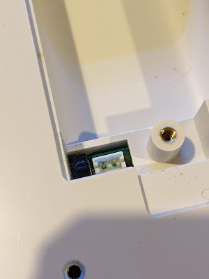
It came attached to the PX-8 and, sadly, when I switched it on I was faced with a sad little flashing cursor rather than the expected boot screen. First thing to check was the cable. This is very neatly tucked away behind a plastic panel on the back of the unit. A quick flick of the screwdriver revealed a rather short and stiff ribbon cable. 

I removed the end from the PX-8 itself and tried to boot but no luck. So I tried to reset the unit by pressing the reset switch on the left side. Still no joy. Then I tried pressing the rest button while holding down the Shift and Num/Graph keys. And to my joy, the PX-8 sprang into life. Sadly though, this means that the RAM disk has issues.

First things first. We need to get it off the PX-8. This was much harder than I imagined and this should have been a warning sign that something was amiss. There are two large threaded 'collets' that hold the unit to back of the PX-8. I managed to undo the first with some difficulty but then the second just would NOT budge. I tried everything I had; a bit of IPA but no change, WD40 but no change, a gentle but nerve jarring tap or two with the handle of a hefty screwdriver. But nothing would move the fixing at all. Eventually, using a bit of brute strength I managed to twist the unit with the non-attached end swinging around and, after a tear inducing CRACK of plastic, it finally released itself. I had damaged one corner of the RAM Disk but it's not too bad and shouldn't be noticeable once it's re-assembled back onto the PX-8 (with fixings loosely attached!!).

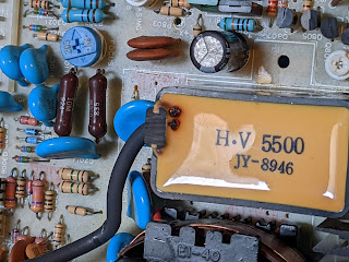
Into the case I went and guess what I saw. A leaky battery. Oh. Shit.

Leaky battery - begone!

At this point I took a slight diversion to also remove the batteries from the PX-8. It involved many screws and much cursing. If it had a screw head, it was undone... 

PX-8 Leaky door - not good

Damaged PX-8 battery connector

Damaged PX-8 motherboard - Gah!

A clean up was made of the PX-8 motherboard which resulted in 'SW3' falling off the board as it was badly damaged. I decided that this PX-8 will not have replacement batteries installed so I could safely bypass the switch so it was always set to "don't keep RAM contents".

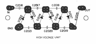
Back to the RAM Disk. This particular device is quite clever as it is an 'active' RAM expansion. In a nutshell, it has its own Z80A CPU and associated logic to control the RAM and the interactions between the board and the PX-8. Very clever. The battery was there so that the RAM could be filled and then, with minimal power required, it could keep the RAM contents. 

Given the age and the use that this board will now have, I again decided that no more batteries would be installed into the unit. No biggie but it does mean I'll probably have to 'format' it every time I switch it on. If that becomes an issue I may have to think again but for now, no batteries.

So, how do we find out what's wrong with this little beauty? I'd like to say I deliberated and came up with a carefully considered plan of simple steps to accurately and quickly diagnose the problem. I'd like to say that but really I've been 'scatter gunning' checks and tests at this a bit willy nilly. Here's a summary though:


RAM Chips

These are fairly standard 64Kb x 1 chips from NEC but they have an additional feature. Pin 1, which is not normally connected, has an extra function. These chips can keep their contents using an extra built in refresh function that uses about 50uA per chip. Nice. This obviously requires that a battery is in the unit but in my case, there ain't gonna be no battery. 

Given that they're standard apart from Pin 1 it was time to break out the RAM checker. I've mentioned this in a previous post so I won't dwell on it too much here. I will add that I put sockets on the board for the non-socketed bank of RAM chips (2 banks of 64kb). I assume that one bank was socketed to allow the board to be used as either the 64kb or 128kb variant.

Heath Robinson RAM Tester

Anway, 2 RAM chips failed. Boo!

But did replacing the RAM chips cure the problem?

No.


Z80A Check

This one was easy. I took the Z80A out of the RAM Disk and shoved it into a ZX Spectrum. It booted fine and ran the SmartCard V2 test ROM with no problems. I even booted up a quick game just to be sure. It's not the Z80A.

The trusty Z80A.

Trace Checks

I have been bitten before by a damaged trace that caused nearly two weeks of confusion. It was an Amiga A500 motherboard and, as it happened, one of the data bus traces was broken. I did not intend to repeat that here, so a few hours of trace checking was carried out. Even though some damage had been caused by the leaky battery it seemed to be limited to the solder mask and all the traces are actually OK.

Still no cure then.


Signal Checks

This time I had access to a more substantial oscilloscope and I put it to use looking at how signals were being handled on the board. For the most part, the signals I found were sensible and a reasonable shape. That was until I reached the TC40H245 chip. Nice crisp signals were going in one side but were coming out very odd shapes the other. Could this be the issue?


Was it the 245, with the dodgy signal,
in the library? (No.)


Not sure this looks right...

Fortunately, I had a couple of these exact chips floating around so after a quick desoldering and socket installation I swapped over to another chip.

Annnnnd..... no difference. It's still broken. :(


Chip Tests

So, other than the Z80A there is an EEPROM and gate array on this board. I can't really do much to check either (although I could dump the contents of the EEPROM - another day perhaps) but what I can do is check the other logic chips. I had to get them all off the board but thanks to my desolder station this was not a big problem. 

I ended up with a pile of chips and needed to work out how to test them. Time to get organised!

Ooooh! Get you!

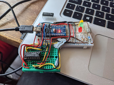
The plan was to wire up each chip and test the various gates and other functions while they were out of circuit. This is where I hit a major snag (and exposed a gap in my knowledge). I wired up a 4069U which is a 'Hex Inverter' so there are six inputs and six outputs, plus a ground and +v pin. Whatever the input is, the corresponding output pin is inverted. So if an input is high ('1') the output will be low ('0'). Or at least, that's the theory. 

When I wired it all up with an LED to indicate the state of the outputs I found I could turn the LED on or off by moving my hands around the chip or by touching the wires. This was completely unexpected and I had to appeal to the Twitterati as to what the heck I was doing wrong. 

In a nutshell, GROUND YOUR INPUTS. I had only connected to one of the gates on the 4069U which left the other input pins floating, causing all sorts of weird and wonderful effects. As soon as I linked all the inputs to ground, the problems went away and I could get on with the testing. 

So from the list, 3C and 13C were fine. But 14C had a problem. This is a TC40H000P which is a quad 2-input NAND gate. This means that there are two inputs per gate and the output is '1' unless both inputs were also '1' in which case the output would be '0'. For two of the four gates the output was '1' no matter what the inputs were. I also noticed a strange 'hot' smell. After utilising my integrated digital temperature scalar unit (my finger) I found that the chip was freakin' hot and clearly up the swanny. Excellent. Or not.


Feeling hot, hot, hot!

13C was the sister chip to 14C and behaved as expected. So did 6C, 4B, 6B and 7C which were also simple logic gates. Nice.

Then came the TC40H074Ps at positions 4C, 12C, 15C and 16C. These are dual 'D' type flip flops and I had to try and work out how to test them. I have worked with flip flops in the dim and distant past but they are but a distant memory.

Eventually I came up with this:

Flip-flop test circuit

So, I put PRE and CLR to high and just left them there, then set 'D' to the input and attached an LED to Q as the output. Every time I toggled '>' (the 'clock' signal') then the setting on 'D' would be copied to the output Q. If '>' was low then no matter how many times I toggled 'D' nothing would happen and Q would remain the same. 

For each of the four dual flip-flop chips I wired them up as above and then did the following:

  • Attach 'D' to 5v
  • Toggle '>'
  • Whatever 'D' was should be on Q so with 'D' at 5v (i.e. high) then the LED should light
  • Attach 'D' to GND
  • Toggle '>'
  • LED should go 'off' as 'D' is at 0v (i.e. low)

Not the most comprehensive of tests but it shows that the basics of the flip-flops are working.

So another four chips tested OK. We are at this point:

Progress!

New 74HC00 chips to replace 14C have arrived and new 14 pin sockets are on the way, so the plan is to install new sockets, the replacement for 14C and see if it that makes any difference.

Stay tuned for an exciting* update soon!

(*this may be stretching the definition of exciting beyond reasonable expectations.)