Monday, May 25, 2020

Unobtanium (next to the Thatwouldbehandium)

Some of you may remember the Interstate console that my awesome Dad gave me a while ago. It was, when presented, a bit dusty. But a good clean and one composite mod later and the thing sprang into life. Almost.

Pardon my (Dad's) Dust

The joysticks were a bit iffy and to try and improve things I ordered a super cheap donor console from eBay. These joysticks were physically the same but, when I dismantled them, I found that they were a few conductors short in their cables and they only had four of the potential six internal connections.

In any case, the joysticks were a suitable donor so I managed, after MUCH swearing and soldering, to get the attached to the correct cables and installed on my now cleaned console.


Joysticks Fully Repaired - About Time!

Pong. Yay!

So, the games on this thing are actually in the cartridges. While this may sound like a newsflash from the Ministry of the Bloomin' Obvious, the cartridges contain pretty much everything. The only thing in the console is the circuitry required to interface the controllers and marshal the video outputs from the cartridge into a coherent video signal. Everything else is done by the chip(s) on the cartridge i.e. the CPU is on the cartridge!

In this case, the '610' cartridge has an AY-3-8610 which contains 10 games. 

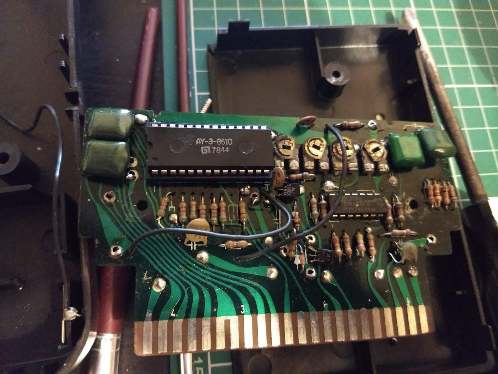
8610 - 10 Games on a chip

Other cartridges were allegedly available, but I had never seen them and I seriously began to doubt that they actually existed. Imagine my surprise then, when one of my eBay searches turned up this:

O. M. G.

Three cartridges, two that I had never seen before! I had to have this and, as luck would have it, the seller sent me an offer that I couldn't refuse. For some reason they only showed the Moto game in one picture which I queried. Apparently, the Moto game wouldn't work but the seller very kindly agreed to throw it in the box in case I could get it to work. Challenge accepted.

After a minor delay in despatch (lockdown and all that), the box arrived. It does mean I have two consoles but that was fine. More spares. But most importantly, all the cartridges were here. 

Squeee!

Hmmm - 604 has been opened... 

I have to be honest, I plugged in Roadrace to check it worked (it did) and then turned my attention to Moto Jump. First switch on attempt gave nothing, as if there was no cartridge inserted. I gave the contacts a good clean with some isopropyl alcohol and tried again. Partial success!

Signs of Life..

Something appeared on screen but I couldn't make anything move. The picture was pretty terrible too. Well, at least there's something to work with, so I cracked open the cartridge.

70's Goodness.

First things first. Change that socket for the AY-3-8765. It was really crusty and horrible. At this point I discovered that forty year old circuit boards are quite fragile. I had to turn the de-soldering station down, just a tad, to stop the tracks from lifting and shrivelling.

Caution - Fragile

I avoided any damage removing the socket and installed the new one without incident, although I didn't have any of the right width. I had to butcher a narrow socket with the correct number of pins, but it worked. :)

Hmm - somethings not quite right...

I won't tell if you don't..

I also noted that there was a logic chip too and it seemed only fair to give that one a socket too.

New socket - invaluable later.
At this point I tried again but ended up with the same problems. Really crappy picture (my display thought it was SECAM) and nothing happening, although I noticed that I could change the display slightly by pressing the 'Program' button. I decided to replace the caps on the board. There were no electrolytics but there were a few ceramics. But this didn't really change much although the picture did seem to become more stable.

So, I decided, what the heck, and I replaced all of the other passive components except for the one variable dude that I didn't have a replacement for.

No change.

I asked for some assistance from Twitter in that I wondered if the 8765 chip in the cartridge could be faulty but still work for some things i.e. changing the game type. The helpful response was that one of the pins, pin 18 to be exact, should have a signal of around 50 to 250khz to indicate the 'throttle' of the bike. If the signal was good there then the chances were, the 8765 chip was toast. Out came the sillyscope.

Well, that's not right.

There was no signal as such at pin 18 which indicated the issue was not the chip but something else in the cartridge. Phew! 

The only other thing I hadn't changed was the logic chip which was a CD4069. This is a CMOS Hex inverter. To determine if this was at fault I built a circuit (shamelessly copied from Google) to test it. Basically, I sent a voltage into one of the inputs and checked if the output was inverted. Pressing a switch would invert (or ground) the input. So, with the switch not pressed, the voltage into the input was 0v and the output would be 5v so the LED would light. If the switch was pressed the input voltage would be 5v and the output would be 0v so the LED would go out.

No switch press, 0v in, 5v out.

Switch press, 5v in, 0v out.

Doing this I managed to identify that pin 11 input to pin 10 output was open circuit so the LED stayed off all the time. By this point I'd spotted that the 610 cartridge also has a CD4069 so I nicked that to try. But I thought I'd test it in my contraption first. Would you believe that pin 9 input to pin 8 output was short circuit so the LED stayed on all the time. Arggghhh!

So, on to eBay to order some new ones. I managed to get three ceramic ones as NOS for a very reasonable £3.95. 

I love the smell of new chips in the morning.
Will it work?

Looks like a throttle signal to me.

Yes. Yes, it did. The game now works as expected. The operation is quite tricky as it needs the joystick to be pushed to the left (no throttle) and then to the right to accelerate. Kids today have it easy with their games. Back in my day etc. etc..


This has to be the rarest purchase I have ever made on eBay. I have had a search on 'Interstate' since my Dad handed over the console about 18 months ago and these are the ONLY cartridges I have ever seen. I'm pretty chuffed to have them in my collection.

Yay!


Post Script - I did the composite mod on the seller supplied console and it was this one that I did most of the testing for the Moto Jump game on. I was quite surprised when I plugged it into my original console to find that the picture was dark green rather than blue. I'm not sure why this is.

Green? Whatever..

Also, I worked out that the reason the picture kept going bad and switching to SECAM was not because of the cartridge. My re-purposed laptop display appears to be very intolerant to slightly out of spec composite signals... A normal TV has no issues.

Finally, I added a potentiometer to the speaker on my original console so I can reduce the volume. The speakers in these things are freakishly loud!


Shhhh!


Friday, November 29, 2019

My Second Apple Foray

Ebay. Love it or hate, it can be a source of some good stuff. In the past I've managed to get two CPCs and a Commodore Plus4 for less than £50 amongst other things. But recently, it's been hard to find anything that i would consider to be a 'decent' price.

Plenty of Amiga A500s but at £90 - £120? No thanks. What about an Amiga A1200? For three hundred quid?? That's almost back to it's original retail price (untested, worked when I put it away..)..

So imagine my surprise when I won an eBay auction for two iMac G3 computers from the late 90's for the princely sum of five of your English pounds. Yes, a fiver. Five knicker. The cost of a couple of large coffees. To be fair, they were collection only, as they are so heavy, and I was fortunate that they were located only about 25 minutes away.

A Right Pair of Beauties
Although the two models outwardly look the same, they are two different versions. There's a 'bondi blue' first generation model, and the next variation which is 'blueberry'. Outwardly there are a couple of more noticeable differences, starting with the CD drive. On the early model the CD drive has a drawer, similar to a drive you might find in any laptop from the early to mid 2000s (but not so much nowadays). The blueberry though, is a 'slot loader'.

My first investigation focused on the bondi blue model. This one is actually an early version of the first generation and I had a vain hope it may include an accelerator card. Sadly, it did not. However, it certainly contained a surprise - but I'm getting ahead of myself.

So, the first thing I did was plug it in and switch it on. I had half expected either nothing, or a loud bang. Fortunately, the only sound was a happy 'bong' that indicated a correct initial startup. The screen lit up and the machine proceeded to boot. Unfortunately, this one had Mac OSX installed which requires a password, long since forgotten by the previous owner. I googled how to sort this out but the method refused to work. In fact, on restarting the machine, it failed to boot, leaving me with a black screen. After a couple of hours of leaving it unplugged I tried again, and it booted!

But then I also noticed that the screen would 'tick' every now again and the screen would flicker slightly. This is bad news as it almost certainly means that the flyback transformer is on the way out, which is a major known issue with these things. There is a slight chance it could be capacitors on the analogue board but this is unlikely. In any case I decided to strip it down to have a look inside.

And then the horror began....

First, the rear cover was removed which revealed....a perfectly clean arrangement of CD and hard drive tray, power cables and monitor cable.

Nothing unusual here

OK. So next, remove the drive bay unit and see what's HOLY MOTHER OF GOD!

WHAT. THE. HELL.
Getting closer doesn't make it look any better..

Oh. My. Goodness.
Well, that was unexpected. The only hint that something might be wrong was that water dripped out of the rear shell. In hindsight, that should probably have given some clue as to the awfulness contained inside. Ok, I suppose I should take the lid off the drive bays and check the OH NO!!

Battery. Feckin' battery...

Graphic image. Discretion advised.
Well, I suppose I should not have been surprised. I suspect what has happened is that the unit has been stored underneath a water source. A leaky roof or something similar. With a heavy heart I started to clean up the board. The batter holder literally fell off in my hand.

The worst battery I've ever seen..
After a couple of hours of cleaning, I was stunned to find that, other than some slight lightening of the solder mask, there was no damage. Really.

Wow. It cleaned up OK.

After wiping and drying out everything that was wet, I decided to dig deeper and see if there was any obvious (!) issues on the analog board. This required me to discharge the CRT and dig much deeper into the guts and is a story for next time....

Tuesday, October 15, 2019

Problems, Problems, Problems

The classic format of a three act play is that part 1 is the setup, in part 2 everything goes to hell and a handbasket and part 3 provides redemption, closure, happy ending etc. My three part story follows similar lines but, in my case, everything goes wrong in this part....

So my A500++ purple beast is complete. I just need to pop him in the A500 case (which my regular readers may recognise as the scarlet Amiga case) and we're done.

First I need to get the current board out. Fetch me the screwdriver!

Get your top off!

Original A500+ Goodness

My favourite - removing hex bolts...

After half an hour of unscrewing, wiggling, more unscrewing, tea drinking and then screwing in many, many screws, I have the purple beast in a proper A500 case with a newly cleaned floppy drive. With gay abandon I plug everything in and switch it on expecting to be greeted by the familiar grey blue Workbench 2.04 as loaded from my external hard disk.

I was to be disappointed.

Dark grey, light grey....yellow. Arse. A yellow screen. What the heck is this? I've seen many yellow screens while repairing Amiga A500s, both Rev6 and Rev8. From my experience this means that there is either a faulty CIA or there is a problem with one of the pins on Agnus. So I undid all the screws, lifted out the floppy drive and swapped the CIAs.

This time I got a guru. I tried turning it on and off again. Yellow screen. Arrghhh!!

Guru, A500+ style...

So, not the CIAs. What about Agnus? I had thought that the socket I had was fine, even though it had been recovered from the old A500+ board. I raised Agnus in the socket slightly by delicate use of a small screwdriver (being careful not to damage the socket). Then went for another switch on. Purple boot screen! Yay!

I had solved all the problems. (Can you see what's coming?)

Except, I hadn't. Every third boot or so from cold resulted in a guru. And if I so much as looked at Agnus the wrong way I was guaranteed to receive a yellow screen at next boot for my trouble. There was nothing else to do, I had to find a different socket. Being the impatient person I am, I basically pinched the Agnus socket from a Rev6 board I have lying around. It was not as deep as the previous socket but Agnus sat down with a satisfying 'click' as I pushed her into its embrace.

Now I have solved all the problems..

Nope. No more yellow screen (so I was confident I was correct about the socket). But every third boot or so I would still get a guru message. This lead me to research what the heck the message was trying to tell me (see HERE for the results of that). Eventually I determined that two main gurus were appearing, one telling me that the CPU received an invalid instruction. This is usually caused by accidentally trying to execute data as the system is looking at the wrong memory location. The other was to do with incorrect crossing of odd byte boundaries which is not permitted on the 16 bit 68000 (it is allowed on later 68k series processors).

The common theme here was memory. So I took out the trapdoor 512 KB expansion and tried again. This time I got a green screen. FFS.

Green screen means that the system cannot initialise the first batch of chip memory. This is normally a failed RAM chip or an issue with the logic between Agnus and the RAM. But I'd already checked the logic chips and replaced one faulty one. To have a RAM chip fail as I put on the A500 case seems too much of a coincidence.

So I took the top case off, removed the keyboard and tried again. It booted. What. The. Heck.

I got hold of a Diagrom from eBay for a few quid to see if that would give me some clue as to what was going on at startup. Unfortunately, it didn't. All system parameters were fine and the RAM was reported as OK.

Your friendly neighbourhood DiagROM
I even tried hooking up the serial output from DiagROM to another Amiga to read the output and see if that would tell me anything extra. Sadly, it didn't but I did learn a lot about DiagROM in the process. :)

Two Amiga 500s ready to talk..
Heath-Robinson Null Modem Cable

Now we're talking...

Despite this I wasn't convinced that there were no issues (guru says otherwise) and decided to look more closely at the RAM. I removed half the RAM and had the thing boot as a 512KB chip RAM machine. Then I spent an hour swapping RAM chips around, putting them into all the possible combinations, trying to see of there was one dodgy chip or socket but to no avail.

As I put the keyboard and case back on I realised that the keyboard was fouling the RAM which I had put into sockets that were, on closer inspection, a bit tall...  After a bit of pushing and prodding I worked out that the left most RAM chip would lift out of its socket when the keyboard was put into place, presumably disconnecting far enough to prompt the green screen. Dangnabbit.

I took the decision to solder the first 512KB i.e. alternate chips, directly to the board. This would guarantee that the RAM would be connected and, having spent a joyful hour chip swapping I was confident that all of the RAM was fine anyway.

Half the RAM soldered direct

This made a difference and it booted without any more issues. So then I re-inserted the trap-door expansion, buttoned up the case and re-booted. Straight into a guru. WHhhhhaaaaattt?

A501 - Ready for action! Or not...

Re-booting brought up the purple boot screen so I tried the Amiga Test Kit which started without any problem. Despite my having the trapdoor 512KB and 512KB onboard the system would only see 512KB. After some headscratching I did a bit of research (via Google) and noticed a lot of advice to check that the _EXTICK (or _EXRAM) signal was present at the trapdoor connector. In my case it wasn't but could be connected via means of JP 7A. Which I did. Which was a mistake. It didn't work and caused me to have a mild panic as I was presented with a dark grey screen on boot followed by nothing... I removed the connection from JP 7A.

I tried cleaning the trapdoor connector as I had recovered it from the original A500+. Sure enough, several pins were dirty or had flux on them from its removal. A bit of IPA and a wipe was all that was needed to get them back to shiny again.

Despite this, nothing changed. The system would still not see the A501. So I put all of the RAM back on to the board making the full 1Mb with half socketed and half soldered. This time, I got a green screen. What. The. Heck.

While disassembling I noticed that one of the socketed RAM chips was making a bid for freedom. This was the final straw. I decided that I would solder ALL of the RAM to the main board.

And that solved it. It has been rock solid since then. I have had no gurus, no yellow screens, no green screens. The lesson here is that sockets are not always good. In my case I suspect that the 'competitively priced' product I ordered and received had a little too much height. Others have reported that good quality turned pin (i.e. round holes) sockets allowed the RAM to be installed without fouling the keyboard. Either way, my problems were solved and I can now enjoy my brand new purple beast.


In summary, the faults I had were:

1) Yellow screen - dodgy Agnus socket; different socket fitted
2) Random gurus - assumed to be a dirty trapdoor connector; cleaned
3) Green screen - RAM chips popping out of sockets; soldered the buggers to the board

Incidentally, I believe that the reason I could only see 512KB with half the RAM on the board and 512KB added via the trapdoor may be down to the system expecting the full 1MB in place before adding the trapdoor memory. That's an assumption on my part but both my 512KB expansions behaved exactly the same way, hence my decision to solder all of the on-board RAM directly to the board.

If you'd like to get your hands on a purple beast, head over to the following link:

https://www.tindie.com/stores/bobsbits/

In conclusion, this board is an awesome achievement by Rob Taylor. Kudos to him and the others who have the passion and dedication to keep the Amiga alive. In more ways than one...

Note: Post edited 24/01/21 to add revised URL for Rob's Tindie store where you can now also buy new C64 motherboards!


Sunday, September 29, 2019

It's Still Awesome - And Now It's Complete!

Brand New A500+ Part 2


It's nice to have new things. A new phone, a new shirt, even a new pair of budgie smugglers (urgh!). It's even nicer when the new thing you have is high quality and better than what you had before. And the A500++ board is very high quality and better than the original in several ways.

First, and most obviously, it's brand new with no Varta acid death and is very good quality - gold plated contacts and a shiny purple finish. Almost too nice to solder anything to.

A Thing of Beauty

Next, any A500+ owner will know that there is an annoying fudge near the 'Audio Filter' section of the board where a diode is soldered at an odd angle. It's a factory mod that corrects a cock-up in the board that was obviously too costly to correct. It stayed that way for the (short) life of the A500+. But the purple beauty solves that issue too.

Other useful things to know are that it has a space for header pins to allow the selection of internal or external drives being connected as DF0, handy for all you Gotek'ers out there. And, best of all, the silkscreen includes many more details not included on the original, of both the component values and also including a subtle nod to the plight of the most vulnerable custom chip when Varta spews forth its poison. 'Poor Gary' indeed.

Improved Silk Screen. :)

Back to my board. One thing I mentioned in the first part was that I was intending to complete this project with as little expense as possible by a) using anything that I had 'in stock' already and b) de-soldering anything else from the donor board. Large items like the power socket, video socket etc are a given. But then there are lots and lots of passive components (resistors, capacitors etc) as well as logic chips and other ICs that I could buy brand new, but the cost of this could quickly add up.

As luck would have it, I had a little bonus from work, and I'd treated myself to a Duratool de-soldering workstation from CPC Farnell just a few weeks ago. And I am glad I did. If you plan to do anything like this, you really should consider getting one of these or something similar. De-soldering a few hundred component legs using a manual pump or de-solder braid would  have taken months. The tool itself is a soldering iron with a hollow core that links to an air pump so, when solder is heated, pressing the trigger activates the pump which sucks the solder into the glass container on the de-soldering gun. I have to tell you now, it took a beating during this project.

That'll need a clean...
Removing components with the tool still took some time. My initial runs with the de-solder gun resulted in many blockages and frustrating delays as I had to keep clearing the glass chamber and the small metal pipe that runs from the tip of the gun into the body. After a while I got quite adept at removing the glass, spring and filter almost one handed, and the delays became fewer and shorter. Some components still required the assistance of a soldering iron to allow their removal. This took a toll on the tips of my iron and I ended up replacing it twice during the removal phase..

That'll need a replacement...
At the back of the main board there is a long row of what looks like ceramic capacitors. They look like that because, in actual fact, they ARE ceramic capacitors but each one has three legs. They are a specific type of cap that (I have to be honest) I had not seen before, known as Feedthrough Capacitors, designed to have an almost ideal insertion loss apparently. Ahem. In any case, removing these took a significant amount of time as they got very, very hot, even with a very small dwell time on the legs. Heat does not do these components any good and I did actually end up with the centre leg of one cap just falling off, and another one nearly splitting in two. The one with the gammy leg was replaced by a willing volunteer from an old Rev6 board I have. Despite this, I managed to get pretty much everything de-soldered without too many problems other than my lack of patience. :)

Some items that I fitted to the new board I did eventually cheat on, and some, as mentioned, I already had. New items I either bought or already had were:


  • New IC sockets* - essential when the custom chips have been removed from a battery damaged board
  • New resistors - I'd intended to use the old ones but then realised how cheap they were and relented
  • New ceramic caps - I already had a box of various values (expect 330nf) so used these
  • New electrolytic caps - already had them all in stock from previous repairs :)

*I didn't have a socket big enough for the CPU so I de-soldered the old one and removed the manky pins. Then I removed shiny new pins from some of the new sockets I had and inserted them into the old socket. I've done this before and it's lots of fun (no it isn't).


Shiny new pins for the CPU

Everything else came from the original A500+ board.

Box 'o bits (one of several)
In all I spent about £10 on new sockets and resistors. Note that to aid future maintenance, every chip got a socket, including the Video Hybrid. This socket was made from slicing a bigger socket in half. :)


Almost done stripping the donor..
The following sequence of pictures shows the steady progression over a couple of weeks....


So, after about three weeks of component swapping, finger burning, de-soldering station unblocking fun, I ended up with this:

Finished! Yay!

Would it work first time?

No.

First test. Board appeared completely dead. I'd forgotten to plug the power supply into the wall.

Second test. Keyboard light stays dim. No display output at all. Then I realised I'd left the Video Hybrid chip unplugged (doh!).

Video Hybrid (the tall thin dude near the back)
Third test. Green screen followed by reset. Bugger.

At least with a green screen, something was happening and it indicated that the system was trying to start up. So, back to diagnosing green screens and an Amiga.... My immediate suspicion was on chips U10, U11, U12 and U13. These are the ones that normally take a big hit from Varta and frequently need to be replaced. I started by swapping them out one by one. Sure enough, the last one I swapped at U13 solved the issue. The SN74LS373 at that location had died, and with a new one the board booted but with an odd colour tinge.

Hmmm. Not quite right...

It was obvious there was a colour problem. In fact, all blue was missing from the image. After a bit of jiggling of the Video Hybrid and other chips I tried again. This time I was missing blue AND green. Everything was red. Dammit.

I removed the modulator and tried the built in composite output which is just black and white but it was crystal clear. So I plugged the modulator back in and tried again. This time I had all the right colours and ended up at the familiar purple boot screen. Yes!

What had happened was that the video socket that was harvested from the old board had acquired a healthy dollop of flux on its pins. Wiggling the modulator in and out a couple of times removed it allowing a full connection and the correct colours to be displayed. Nice.

Ahh! That's better!

So, next test. I plugged in my trusty AlfaPower external hard drive.

Old Faithful!

Would it work?

Success!
Yes. Yes it does work.

Now all I need to do is pop it in the case and everything will be fine.

     Or will it? (hint - it wasn't)

To be continued.....