Tuesday, January 22, 2019

What do you mean I can't title this post "Whats that Pong?"...

..as RetroManCave already used it?


By sheer coincidence, one of my favourite YouTubers did a video on a Pong clone that used an AY-3-8500 chip as it's core. I too, have one of these which I got before Christmas from my Dad. Mine, however, is a little bit different.

Presenting the Interstate 1125 console from 1978 with around 30 years worth of dust! This was THE first games console that our family had and I remember sitting in front of the our ancient CRT TV (with fake wood case and manual tuning knobs) with the mini analogue joysticks and a single, tiny red fire button trying to hit more crosses or score more goals than my twin brother. 

Anybody? No? Dust? Anybody? No? Dust?

Memories aside, there are several interesting points about this console. It has cartridges which is unusual for this brand. The suggestion is that more cartridges would have appeared to slake our thirst for more, and bigger games. Sadly, while others may have been available, we only had the 610 cartridge. I was quite surprised to see while preparing this post that there were at least four other cartridges available, the 601, 603, 604 and 605. 

First things first, I need to find a power supply. Fortunately, my multipurpose supply that I use for my oscilloscope has the right voltage and has the right adaptor - which is rather bizarrely a 3.5mm single pole jack i.e. a mono headphone plug.

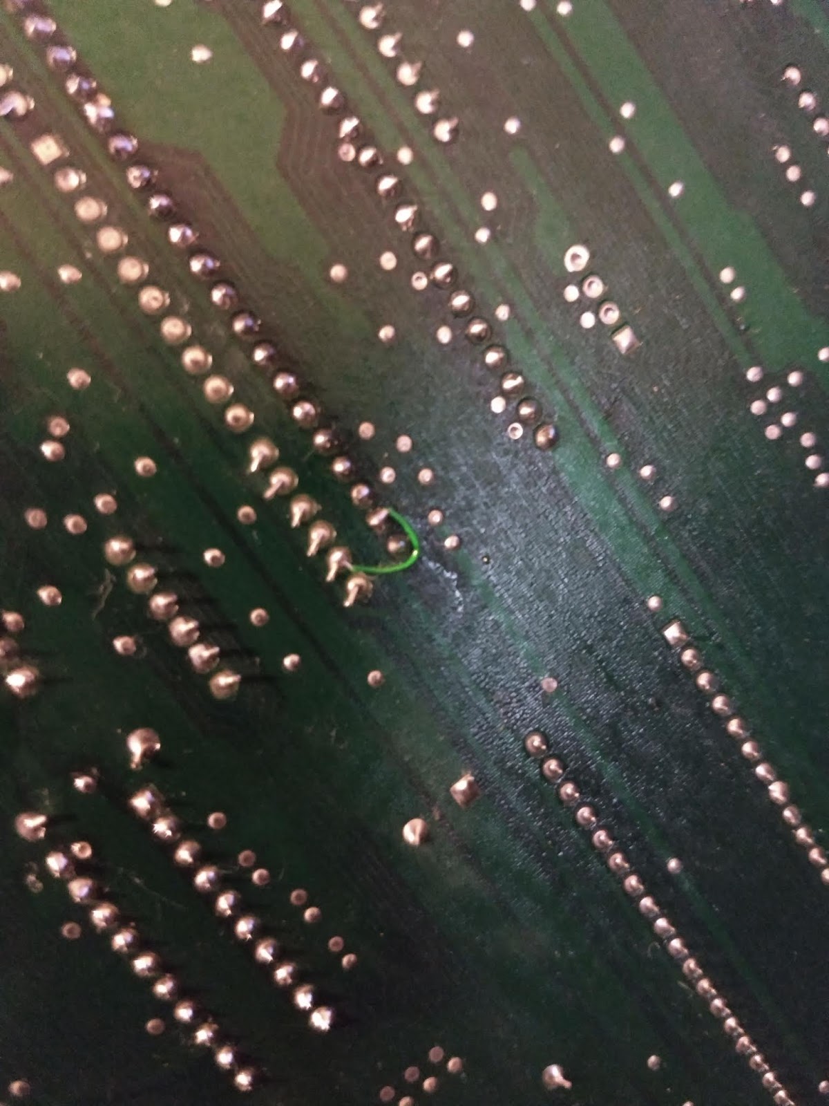
Next, this thing will only output RF and, somehow, I need to modify it to do composite as my LCD panel will only take composite or HDMI. Having done this before on the Spectrum I had a hunch that it would be very similar i.e. disconnect the RF modulator and re-connect the input straight to the centre pin of the video out. 

Let's get that top off. First problem was the cartridge which, having been in-situ for NEARLY 40 YEARS didn't want to come out. A few minutes of gently pushing, pulling and wiggling finally released it. I wondered what was inside....(side quest incoming)...

Ohh, look at that!
Inside is an AY-3-8610 chip, manufactured week 44 of 1978 (for reference I was four years old at the time). This is an interesting beast as it is a dedicated 'pong on a chip' developed by General Instruments. They were fitted in several pong type consoles, although the 8610 is actually an improvement on the 8600 which itself was a later development of the 8500. Interestingly, a chap by the name of Cole is working an an FPGA emulation/recreation of said AY-3-8500 chip. See his blog here.

As a sidenote, the cartridges mentioned above most likely have other variants of these chips installed in them. From information on Cole's blog (actually at pongstory.com), there are also chips 8601 to 8607 all with different games baked into them..

Anyway, after putting this cartridge back together, out came the wire cutters and soldering iron. After a few minutes puzzling over exactly which connection would be the composite input to the modulator (it really shouldn't have been THAT difficult!) the mod was made but the question was, would it work?

So, we have power, we should have video and the only thing left to do was to switch it on and see if it would work.

BUT before we do - who the hell designed it so the power connector is the same type and size as the 'pistol' connector and are RIGHT NEXT TO EACH OTHER??


After making sure the power jack was in the right place....success!

Playing with..er..against myself.

Mrs Crashed loves how tidy my desk is.
Sort of. 

The video works without any problem at all and I'm really pleased with the output on my re-claimed laptop LCD panel.

But, the right stick doesn't work. And the 'programme' button doesn't either. Bugger.

A bit of fiddling and the programme button suddenly sprang into life. Probably just some more dust.. Cycling through the games was a trip down memory lane and an eye opener for my 13 year old who is more used to 3D open world shooters (yes, Fortnite). When I say 'eye opener' what I actually meant was that he rolled his eyes at my cackling at getting this partially working.

Anyway. The joystick. On this model the joysticks are actually connected via a DIN plug into the top of the console. Other Interstate consoles, those that did not use separate cartridges, had their joysticks or paddles wired directly into the main unit. They all use a handy storage system where they click into place on the case though, which I actually quite like.

The construction of the joysticks is fairly crude but they are analogue sticks. Two potentiometers are mounted at right angles and the movement of the stick is translated via a simple gimble. The fire button is a standard momentary push switch. The left joystick works without any problem except for the fire button being a bit sticky. The right joystick did not. It would occasionally show up and down movement but there was no left/right movement at all.

Dismantling the faulty stick completely, revealed that the potentiometers had some corrosion (liquid ingress maybe?) and so were unlikely to work ever again...

Dismantling
(Yes, I can see a wire's come off!)

Potentiometer separated
What to do? Well, they seemed to be 100K ohm pots and I did have some of a similar design. Sadly, they didn't fit and I think the ones I had were linear rather than logarithmic. I managed to wire them up on a breadboard and manually twiddle the pots but, apart from being not a great way to play a game, they just weren't quite right.

The problem is that pretty much all of the games on this thing require two players so only having one working joystick leaves it pretty useless. So I have taken a gamble to bag some spare parts. I have got a cheap Interstate console on the way via eBay. It's not the same model BUT it does use the same joysticks. Its an Interstate 1110 whereas my unit is an Interstate 1125.

Next time... we find out if the joysticks really ARE the same.


Saturday, January 19, 2019

The (Joy)Stickiest Situation Since...

...Sticky the Stick Insect got Stuck on a Sticky Bun


NOTE THAT THE INFORMATION HERE IS NOW A FEW YEARS OLD - THERE MAY BE BETTER WAYS TO DO WHAT I DID HERE, WHICH CAN ONLY REALLY BE CONSIDERED A 'HACK'. FEEL FREE TO READ ON AND USE THE INFO AT YOUR OWN RISK....

I have never owned a Commodore 64. I would love to but the hardware can be expensive and some parts are becoming R@RE!! L@@K!! and difficult to find, especially the SID chip and PLAs. So the C64 Mini sounds like it would be an ideal substitute. For the bargain price of £45 in the Amazon sale, Mrs Crashed bought me one for Christmas.

 
My C64 Mini 

Many things have been said about this baby C64 and there are lots of reviews so I won't bore you with unboxing pics or my own review. Check out the reviews from The 8-bit Guy and others if you want that.

8-bit Guy - Initial Review
8-bit Guy - Review of NTSC version
Nostalgia Nerd

This blog is specifically about the joystick supplied with the C64 Mini. To be blunt, it's crap. It's styled on the Competition Pro which is regarded as one of the best joysticks ever. Sadly, this version is a pale imitation of such greatness. Gone are the positive microswitch clicks, to be replaced by a vague squidginess which is distinctly uninspiring. Don't get me wrong. I appreciate that this type of thing has to be built to a price point and the overall experience is very well executed, especially with the latest firmware updates. But the joystick just isn't very nice. Or very strong. Several reports have appeared of the stick actually breaking off at the base of the shaft following a particularly vigorous waggling.   Ahem.

Ouch!

Double Ouch!
So, what to do?

Take it apart and have a look inside. That's what. And lo and behold, the main board in the stick contains individual rubber buttons for each direction and for the fire buttons. This means that the main digital functions in this stick operate the same as any other Atari style stick. I had a thought that maybe I could wire up a joystick port and hang it out of the side. That way, I could connect a decent joystick for playing a game and just keep the provided one for menu selection. And I wasn't the first to think this either.

On the C64 Mini Facebook group there were already pictures and diagrams of how to add a DB9 port to the C64 Mini stick. Nice.


So, here's my experience. You can think of it as a tutorial if you like. It's not intended as such but I shall try to make it so that you can follow along with what I did and the problems I had. No responsibility is accepted if you attempt to follow this and you end up damaging your C64 mini, crashing your car or blowing up the cat. Note that your warranty will almost certainly vanish in a puff of smoke so this is not for the faint hearted.

First things first, I needed a DB9 male plug. I have a bag full following a 'misorder' while I was replacing an Amiga mouse port. They are board mount but will do the job with careful soldering.

 
Yep, it's a DB9 plug...

Next, I need to work out which wires would connect to which pins on the back of the connector. As luck would have it, I built a joystick tester over Christmas so I had a perfectly good diagram already drawn with the pin outs. I modified it for this purpose once I had the board out.


My corrected diagram!
(First attempt had an error!)

I dismantled the stick and removed the board. Then I took off the silicone pads/buttons. Note that the fire pads/buttons on my unit were a different colour to the direction buttons and need to be replaced in the same location. Put them safe.

The board should have a small copper pad next to each direction and next to the fire buttons. I soldered a wire to each pad being sure to make them over-length so it would be easier to put the plug where I wanted (but see below).

Then, using the diagram, I soldered the other end of each wire to the correct pin. Note that the ground connection also needs a wire. Its the black wire on the main cable into the stick. On my unit there was a solder pad helpfully tucked behind it. Also note that if you're following the Atari standard then only one fire button should be connected to Pin 6 on the DB9 plug. On my stick this was the one labelled S1. The other switch labelled S2 can be connected to Pin 9 on the DB9 plug which will then support two button type joysticks although I think that these are quite rare.

All of my connections are red, except for the ground wire which I used blue.

Wires Soldered in Place

So now you should have a board with an unsightly plug hanging off it. At this point I decided to test mine and found a bit of a serious problem. I plugged in my ZipStick and switched on the C64 Mini.

  • No smoke? Check.
  • No unpleasant burning odours? Check.
  • No fuses tripping? Check.
  • Display appears? Check.

But as soon as I clicked 'right' on the ZipStick the cursor kept going, even after I let go. It wouldn't stop and rendered it unusable until I reset the whole thing or pulled the ZipStick out. Hmmm. Curious.

A quick visit to the Facebook group revealed that this is a known problem. For some reason, the length of the cable causes the C64 Mini joystick controller to get confused when a button is pressed. I still don't fully understand why but if I find out, I shall add a note to the bottom of this post.

Now, I collect various bits of retro computer stuff and there was no way I was about to start chopping up the cable of my precious ZipStick. Fortunately I had a spare cable from a really old and really crap joystick which I just cut off. My initial thought was to wire in the shorter cable with the original cable in-situ but after a bit of faffing I found that this made no difference. The presence of the original cable still seemed to be causing problems. However, if I removed the original cable completely and then tried the short one the ZipStick worked fine. Go figure. So, I soldered the super short cable into my ZipStick and put the original away safe.

With testing complete it was just a matter of mounting the DB9 plug inside the case. This is where I hit problem number 2. A couple of my initial cables were too short to allow me to mount the plug at the back of the stick. I wasn't about to de-solder everything again so I did the only thing I could. I mounted it on the side. :)

First I drilled several holes in the rough shape of the 'D' of the DB9. Then with a strong blade I cut through the holes are removed the plastic from the initial hole. Then I took a smaller blade and carved out the plastic until the shape was large enough to accommodate the DB9 and filed down any sharp edges. I then marked the location of the two screw holes and drilled to allow the bolts through. A couple of the internal braces on the top and bottom case had to be cut off to allow the plug to fit but this was easily accomplished with a pair of wire cutters.

Then it was a simple* case of pushing the plug into the hole, lining it up and screwing the bolts in.

*simple if you have three hands.


Anyone have a spare hand?

Hole gouged out...but successfully mounted. :)

Finally, I put the main unit back together. This was not as easy as it sounds as the little red buttons kept falling out. And then the cables kept catching in the screw posts. Sorting that out then jiggled a couple of buttons out of their slots.. and so on. This bit took me about fifteen minutes of contortion and swearing but I got there in the end. And it doesn't look too bad.

Installation Complete

Just plug in any standard DB9 joystick.

Bear in mind that by mounting in on the bottom half of the case (which is simple as it has loads of room) the plug is pointing down. So when a joystick is plugged in, it will push the side of the C64 stick upwards. This isn't a huge problem but something to remember.

And that's it.

For information, the cable on the ZipStick is 48cm or just under 19 inches in length from the end of the plug to the body of the stick. Your mileage may vary.

A happy by-product of this escapade is that, because the C64 mini joystick is a fully fledged USB game controller, plugging in the ZipStick allows me to use it on my modern Win10 PC! Nice.

Here's some more pictures that I took which may be useful for someone:


I've just spotted a slight problem with my wiring. Nothing drastic! I have wired button 2 to pin 5 instead of pin 9! Doh! Fortunately, pin 5 doesn't do anything and, as I don't have any two button joysticks I shall probably leave it as it is. :)

I've now corrected the wiring as there was an issue with the original post relating to the S1 and S2 pads and the pins that they connect to. S1 should be pin 6 and S2 to pin 9 as shown on my fancy (not fancy) drawing diagram thing back up there somewhere.

NOTES
In my original diagram I had S1 from the C64 joystick going to pin 9, but it should go to pin 6. And S2 is shown as going to pin 6, it should go to pin 9!!  I found this out as the Zipstick I used works fine on the C64 Mini but DOESN'T work properly in WinUAE. This sees the Zipstick fire button as button 2.

I guess that the C64 mini just translates either button to be 'fire' but WinUAE is specifically looking for button 1 to come out of the USB and I've inadvertently connected up button 2 instead..


Saturday, December 15, 2018

Which one's best? There's only one way to find out!

A reasoned debate based on empirical evidence and documented experience...


There are a lot of retro computer collectors out there. There are several reasons I know this.

First, there are a lot of them on Twitter and one or two may actually follow me there. I certainly follow quite a few.

Second, the price of retro stuff, and in particular Amiga items, has skyrocketed in the last three or four years as more and more people start collecting. Supply and demand and all that.

To give you an example, I paid around £170 for an A1200 in a Micronik tower (the all plastic one) with a Squirrel PCMCIA SCSI interface and four speed SCSI CD-ROM drive. This was in 2015. Today, on eBay, a stock A1200 that hasn't even been re-capped will set you back at least £200. A CD32, boxed, re-capped and fully working with a controller will set you back at least £400. And that was it's original retail price in 1993!

With the continued inflation of Amiga prices I have been unable to buy many things (under penalty of divorce) so I have had to go with several other systems, some I already owned but mostly acquired from lucky bids on the aforementioned eBay. It got me thinking that someone who is setting out to acquire some retro computer kit may not know where to start or which machines are good to begin with and which are not.

So, what follows below is my own meandering experience of retro computers. It is not intended to be definitive or instructions on how to collect. Nor is it intended to be a tutorial for repair or anything like that. Take it at face value.

Let get on with it. Machines what I've worked on (click on the titles to take you to a blog post):

Amiga A500 and A500+
Although prices for A500s are rising, possibly due to the limited chance of getting an A1200 for a decent price, but also possibly because Vampires are now available for them, they are still a good machine to start with.

My own A500+ with hard disk & external floppy.
Battery damaged board but repaired.

If you're completely new then try and avoid cheapish looking A500+ models. These will almost certainly have battery damage from the dreaded Varta that was installed on the Rev 8 models. This is shown by green corrosion and fuzz around the normally blue battery casing on the motherboard. The more sharp eyed will also spot that the trapdoor connector usually also shows signs of the green rot too..  Unless you get one that specifically says the battery has been removed and cleaned up then stay away. Perhaps you like a challenge...

Other common faults with A500s are busted CIAs resulting in dodgy mouse or joystick control, and the failure of the floppy drive. These are normally straightforward fixes. These units also have a terrible problem with going yellow in the sun which is a common issue with most beige electrical kit of this sort of age.

Software is (was) relatively easy to find but might become harder now that Nintendo have started to come down on ROM sites.

A hard disk is a good thing to have but original units are also getting quite rare. Something like a GVP or AlfaData AlfaPower drive will add an extra level of functionality. The AlfaData external units also can come with Fast RAM (essential for WHDLoad) and are IDE units allowing the use of cheap Compact Flash card adaptors.

A500+ Motherboard

Repairability:  8/10
Most chips are socketed and it's easy to open up and have a good poke around. Very rare to have a capacitor issue on these too.
Price: 7/10 
They're going up! Expect to pay anywhere from £35 to £90.
Overall Collector Score: 8/10


Amiga A1200
The successor to the A500 (I will ignore the ridiculous A600) and with extra RAM, a slightly faster processor and the new Advanced Graphics Architecture (AGA) chipset, these are very, very desirable. Accelerators are were relatively easy to find (but getting harder) and can add a level of 'oomph' that I only dreamed of in the early 90's.

It's...an A1200

The A1200s (and 600 and CD32) suffer from the problem of cheap capacitors. They are surface mounted pots of electrolyte that leak over the board and slowly eat away at the copper traces. They can cause the complete destruction of a motherboard so, again, if you're picking one up for the first time, you should check for if it's been seen to. There's no battery in the stock A1200 but if you're lucky enough to get one with an accelerator card in it then there's a good chance there's a battery on there - remove it quick!

Capacitors not sitting flush.
Danger Will Robinson!

Price is the main problem here. As I mentioned above, a stock A1200 will set you back around £200 which will probably not even be re-capped. For that price it's 50/50 as to whether you'll need to break out that soldering station and get fixing.

Repairability: 6/10 
It's all surface mount in there so you need a steady hand or specific equipment..
Price: 6/10 
I love these machines but who in their right mind would pay that much for them?? Expect to pay over £200 for even the most 'untested' of machines..
Overall Collector Score: 6/10


ZX Spectrum 48K
The venerable ZX Spectrum was the first computer that our family owned. In actual fact, we had a ZX Spectrum+ which was a slightly improved 48K model but which also had a half decent keyboard with a space bar in the right place and a reset switch.

Spectrum 48K Interior
This is an Issue 2 motherboard

As with a lot of things on this list, capacitors can be a problem. In this case they're all 'through hole' and so easier to work with but, be warned, the boards of the spectrum are more fragile than later machines like the Amiga. Exercise care if you decide to re-cap.

Other problems include broken RAM. This is normally caused by the failure of the voltage regulator on the motherboard or the DC-DC circuit that generates 12 volts. The lower portion of RAM requires +5v, -5v and 12v to operate correctly. Any missing voltage will damage the RAM. It doesn't even need a complete failure to cause this either. Look for garbage on the screen when it starts.

The ULA (Uncommitted Logic Array) chips can also die in these so, if you can, try before you buy.

Certain motherboard revisions benefit from later mods. For example, the issue 2 - which has its heat sink located in the bottom right of the motherboard - can have a mod added to the DC to DC circuit which improves resilience to voltage spikes caused by unplugging expansions with the power still running (don't do it!).

Finally, the keyboard membranes regularly fail due to their age. Fortunately new ones are available and tend to be made from modern materials which should improve their durability.

Broken keyboard membrane

Repairability: 7/10
Everything is through hole so a standard iron and a steady hand is all that's needed. Just be careful of the slightly more delicate traces!
Price: 9/10
Spectrum 48K models in an 'untested' state can be had anywhere from £20 so they won't break the bank. Get one with a tape cassette player and cables if you canA great place to start and a fine piece of history too. Also consider the +2 and +3 models although they tend to be much more pricey - especially the +3.
Overall collector score: 8/10


Amstrad CPC464
To be honest, the first CPC464 I owned was acquired only a few months ago. In fact, I actually bought two as part of a job lot of stuff which included the Plus4 (see below). I was very pleasantly surprised to see their build quality, not a thing Amstrad has necessarily been renowned for, and was very happy that they both 'just worked'.

CPC464 - Later model with angled stripes on logo
My dodgy camera makes this look bent - it's not

If you get one of these the first thing you should do is change the cassette drive belt, unless it has already been done. This is always the first thing to perish as it is, after all, basically a glorified rubber band (don't be tempted to use a rubber band though - it won't work and could make things worse!).

I have seen no major reports of problems with the chips in these things. General issues could be caused by a dodgy RAM chip or a potential ROM problem but, overall, these things seem to be bullet proof. And there are no electrolytic capacitors to worry about! Every capacitor is ceramic. :)

They do use a membrane keyboard on all but the earliest of units, but the two I had were still using their original membranes and all the keys worked with no issues at all.

You could also consider modding these to accept a MIC input which will allow the use of *.TAP files to load games from your phone or favourite generic MP3 player rather than physical cassettes which is easier and can be a bit faster too.

Repairability: 9/10
A few screws to undo and easy access to everything on a good quality PCB with all through hole components. Nice.
Price: 8/10
Expect to pay about £40 to £50 for a working CPC464 without a monitor. If you find one that comes with a monitor then add another £40 or so for monochrome or £60 to £80 for colour. Other models like the CPC664 or CPC6128 are also around but expect to pay a premium for their floppy disk capability.
Overall collector score: 9/10


Commodore Plus 4
The Plus4 is an odd beast. Released as a 'replacement' for the C64 despite not having the famous SID chip for sound, reliable components or good software support, it unsurprisingly failed to capture the previous glory that Commodore enjoyed with the C64 or even the venerable Vic20. It was reasonably successful in Europe which provided some relief to the sales guys at CBM but failed miserably in the US.

Full disclosure. These things fail. A lot. They have a non-standard variant of the 6502 processor known as the 7501 (early) or 8501 (later). When they were produced mistakes were made in the production and design and so these chips die just through normal use. Some died within hours, some within months. Some lasted a bit longer but most will die soon.

They also have what is called a 'TED' chip. These things also die. And are almost impossible to find replacements for.

If you're tempted by one of these and end up getting one, the first thing you WILL need to do, assuming it works, is take it apart and put the biggest heatsink you can find (and fit in the case) on both the CPU and TED. The ROMs can get quite hot too.

Plus 4 interior carnage
CPU - DEAD (replaced with 6510 adaptor board)
8551 serial chip - DEAD
RAM - 2 chips DEAD
Plus4 ROMs - DEAD
If you have one with a black screen then you're too late. You have either a faulty CPU (75% chance) or a faulty TED (25%) chance. Garbage on screen could indicate faulty RAM or, as was the case with my own Plus4, the 8551 interface chip was spewing garbage on to the main data bus causing all sorts of bizzare things to happen.

I would not recommend this to a beginner collector, which is a shame as I like the design and there are some cool things you can do with them including an SD2IEC implementation - this is Commodore kit after all. But the chances are if you get an untested unit it will not work and those replacement chips are getting more expensive IF you can find any. The CPU can be replaced by a 6510 (as in the C64) with an adaptor board but there are a couple of technical limitations i.e. the computer won't be able to directly control the tape deck, the tape deck motor runs constantly, a new Kernal is required - but this is normally supplied with the adaptor board.

Repairability: 4/10 
Nice and easy to get into, nice and easy to remove the dead chips. Shame there's not much to replace them with...
Price: 6/10
These units are going up in price for some reason. I would not consider paying more than £30-40 for a working unit. Chances are, if you start it up, it will work for five minutes then become a non-working unit anyway - get those heatsinks in and pray.
Overall Collector Score: 4/10


Apple Mac Classic II
This one came to me via a nice chap in Worcester and I'd originally intended to restore it and use it 'properly' but, sadly, I had to sell it on. These units come with a CRT monitor built in so any repair work needs to be treated cautiously as these things hold high voltages and currents that can kill.

Early Mac
Units like this one appear on eBay regularly but be careful about battery damage. They have a small lithium non-rechargeable battery on board which can leak and completely destroy the main board. Caps are also an issue, similar to the Amiga A1200 (and A600 etc) being the surface mounted electrolytic type. The motherboards are good quality though, and the unit I had the motherboard went through the dishwasher(!) with no ill effects.

The biggest issue with these things is getting the software. Unless you have an older Mac that has both floppy drive and USB then you will struggle. While I was restoring this unit I inadvertently managed to wipe the first 1MB of data from the main partition of my Windows 10 PC, rendering it er..dead. So proceed with caution if you're forced down the PC route for disk preparation.

Finally, the hard disks on these units die very easily. If you get a unit with a working drive, do not trust it. Fortunately, the Mac Classic II uses a standard SCSI interface so any drive of an appropriate size will do but - again - be aware that you'll need third party software to prepare the drive or a patched version of the Apple software. Apple helpfully wrote their software to only work with Apple branded hard disks... the more things change, the more they stay the same.

Repairability: 6/10
Surface mount stuff but the boards are hardy beasts as long as they have avoided battery damage. Be prepared to lose hair and sanity when trying to get the software working though. AND STAY AWAY FROM THE HV CIRCUITS IN THE CRT!!
Price: 7/10
Not too expensive these days for an 'untested' unit. Expect anything from £20 to £80 depending on condition and whether or not the buyer has to ship it. If you can, find a local one so it can be safely belted into the back of your car.
Overall Collector Score: 6/10


As with all things like this, your mileage may vary. Prices vary wildly on eBay to the point of insanity. My favourite is the guy in Scotland who puts his standard A500 (ready to go! UNTESTED) on eBay every so often for £1000. Yes, a grand. The popular theory is that he's been told by his other half to get rid of it and is 'going through the motions'.

Finally, if you are looking to start collecting retro game systems then, good luck, don't spend too much (unless you want to) and enjoy the systems for what they are.

Merry Christmas!

Monday, October 29, 2018

Simple Logic (Captain)

One of the more useful tools when trying to troubleshoot faulty boards is a small, innocuous thing that is known as a 'logic probe'. So, what does it do? It probes logic, obviously.

What it actually does is give an indication of a logic level. Computers work on ones and zeros. A logic probe simply indicates if the point where you, ahem, stick it is a one or a zero. It's really that simple. And I don't have one. Of course I could buy one, but where's the fun in that? :) So I set out to build a simple logic probe from anything I had lying around.

First things first, lets think about a circuit. Fortunately, I didn't have to think too hard as a helpful youtuber called Aldrin Floyd created a very short video showing about as simple a circuit you could imagine to produce a working logic probe. See his video here.

The schematic he came up with is shown below:


It's operation is simple. When the probe is placed on a low signal, the transistor is completely off, resulting in the full voltage being shunted through the red LED to ground through the probe. Boom. Red LED lights up bright. When the probe is placed on a high signal, the base of the transistor becomes saturated by the probe and allows the flow of current straight down to ground through the green LED. Boom. Green LED lights up.

(When there are no signals, both LEDs light up quite dim, which I assume is because the voltage drop across the resistor and red LED is enough to allow the transistor to partly turn on which, in turn, allows the green LED to turn on slightly. I'm sure an electronics expert would be able to explain it better than I can.)

 A strobing signal also lights both LEDs but is easy to distinguish from the 'just on' state as both LEDs become significantly brighter (with red actually being the brighter of the two).

A list of parts required:

  • A stiff piece of wire or a brass road of about 2mm diameter (for the probe)
  • An NPN transistor
  • A red LED
  • A green LED
  • Two 1k ohm resistors
  • Some wire (two core about two feet)
  • A couple of crocodile clips

First, take your probe and file the end into a point - the pointy end will be the bit you use most
Solder the Base of your NPN transistor to the probe.
Then, solder one of the resistors to the collector of the transistor.
Next, solder the positive lead of the green LED to the other end of that first resistor
Now, on to the red LED. Solder the negative lead of the LED to the probe.
Then solder the second resistor to the positive lead and the end of the resistor to the emitter of the transistor.
Nearly done.
Take one length of wire and solder it to the point emitter and resistor meet.
Take the second length of wire and solder it to the negative lead of the green LED.
Solder a crocodile clip to the other ends of the wires.

Annnnd.... you're done.

Once done, it should look something like this:

Bottom View

Top View

I did this in about twenty minutes and, having coated it in hot-snot to prevent shorts, it's ready to rumble. It's not pretty, I'll give you that.

Hot Glue Gunned

So to test. I took an Amiga A500 motherboard and connected the croc clip from the transistors emitter (the positive) to a positive supply rail on the board, and attached the other croc clip (the negative) to an earth point on the board. At this point, both LEDs light up dimly.

To check it was working I probed the positive lead of another cap on the board. The green LED lit up brightly and the red LED went off. Then I probed another earth point on the board and the red LED lit up bright and the green LED went off. If data lines are probed which are normally 'strobing' then both LEDs light brighter than when in their quiescent state but not quite as bright as a steady high or low signal.

A 'high' signal

A 'strobing' signal

A 'low' signal


And that's it. It's primitive and I'm sure that there are probably better circuits out there but for what I need, it's perfect and almost completely free. To pay lots of money would be illogical. Captain.

Friday, October 12, 2018

Back Home In...A500+ Land

After my foray into the CBM Plus4 (the worlds most fragile 8-bit computer) I have acquired another A500+ motherboard with battery damage. This feels like coming home and, after the confidence bashing of the Plus4, I've picked myself up and I'm ready to DO THIS! C'MON! RARGH! YEAH!!

Ahem.

Oooh - a parcel! What's inside?

It's only an A500+ motherboard with Agnus and ROM!

This time the actual board looks relatively unscathed. The same, however, cannot be said for Gary's socket. The pins are green and, er, mostly gone. Just touching the spring contacts resulted in them disintegrating... But amazingly, the solder mask has not been damaged at all which leads me to suspect that the Amiga was stored standing on end and leaning with its keyboard facing towards the floor.

I spy with my little eye...a borked Gary socket

But no solder mask damage. Hmmmm...


Anyway, this is another 'on the cheap' repair i.e. I have to do this with no additional parts other than what I have available from my previous escapades. Bear this in mind as you read on.

First things first, get Gary's socket off. Now, I don't have a lot of luck removing large chips from boards and I don't know why. It just seems that I haven't got the knack of removing solder completely from the pin holes. I've had some more luck with expensive solder wick but that is, well, expensive. So, I'd decided to bite the bullet and cut Gary's socket off as cleanly as possible with the intention of gluing it back together.

"But what about those disintegrated pins?", I hear you cry. Well, I have somehow ended up with a surplus of 16 pin DIP sockets which have the same style of pins. They are small pieces of spring metal that are pressed into the holes in the plastic socket. It's simple to remove them from the 16 pin sockets and re-insert them into Gary's socket. It is very tedious and I had promised myself I would not do this ever again. But needs must. See here.

Pins, lots of them...

After carefully gluing Gary's socket back together and then re-inserting the pins I soldered it back to the board. Didn't he do well?

As bright as a shiny new pin(s).

With Gary's socket back on the board I checked to see if there were any broken traces. Another chunk of time taken up with continuity checking, but worth it as I identified one missing connection which was simply fixed with a small wire.

Broken Gary trace - strange, but fixed.

Time to dig out the rest of the chips. The board is a straight swap with one of the guys on the Amiga FB group so we did it 'chips out' so to speak. After fishing them all out of the box, and checking I had the right ones - Denis and Agnus are ECS and I have some OCS chips in my spares box - I was ready to rumble. So, the first attempt to boot. Does it boot?

No. Green screen.

Here's a description of the Amiga boot colours, taken from the classic Amiga wiki.

When the Amiga boots, if it encounters a hardware fault the system will display a solid single coloured screen, or a series of these screens if more than one error is detected.
The following colours are valid for all versions of AmigaDOS since Kickstart 1.3. However, there were several more colours in 1.3 compared to anything included after Kickstart 2.0 was released. However all of the colours listed below are the same for all versions of Amiga kickstart.
  • Red - An error in the Kickstart rom as detected.
  • Green - An error in the Chip Ram was detected.
  • Blue - An error in the custom chip set was detected.
  • Yellow - The CPU encountered an error before the system's error-trapping code (the code the calls up the Guru) was in place.
  • Black - No CPU detected.
  • Grey - CPU Passed the test.
  • White - CPU failure.
In addition to colour screen error codes, Guru Meditation error screens are also a common error screen encountered when an Amiga encounters a problem

This is helpful but doesn't give much detail. All I can glean with a green screen is that my chip RAM may be borked. But Agnus may be faulty, or it could be a damaged trace or it could be something else. There is more information available on the actual sequence of startup:

Taken from Lemon Amiga at this link. I've reproduced it here as this type of info has a habit of disappearing over time...

Amiga Boot Sequence 

1. Clear all of the chips of old data. 
2. Disable DMA and interrupts during the test. 
3. Clear the screen. 
4. Check the Hardware to make sure the 68000 is working. 
5. Change the screen to Black, screen stays Black (or with red Stripes) if CPU fault. 
6. Do a checksum test on all the ROMS. 
7. Change screen to Red if ROMs are faulty, or change to Dark Gray if ROMs are OK. 
8. Begin the system startup. 
9. Check the Ram at $C0000, and move SYS_BASE there. 
10. Test all of the chip RAM. 
11. Change screen colour to Green if RAM is faulty, or change to Light Grey if RAM is OK.
12. Check to see if the ROM software is coming in OK and being executed. 
13. Change colour to White if the software test is OK, stays Light Grey if faulty, or Blueif Custom Chip error. 
14. Set up the chip ram to receive data. 
15. Link the ROM libraries so the machine can identify connected devices and peripherals. 
16. Check for additional memory in these devices and link it to the computer. 16b. Chance screen colour to Yellow if there is an error with external cards/devices. 
17. Turn the DMA and Interrupts back on. 
18. Start a default task. 
19. Check to see if there are additional CPUs on the system, accelerators or a maths coprocessor. 
20. Check to see if there CPUs are OK. 
21a. If there is an Exception (processor error), or issue reported, the system will reboot. 
21b. The Kickstart Image is Displayed showing that the rom has been installed to memory, is running, and everything so far has reported OK. 

After this, the ROM GURU trap handler will display errors as codes on the screen. 

My A500+ board fails at step 11 i.e. the chip RAM check failed. No great advance there. After poking around at the logic chips (U10, U11, U12 and U13) it was obvious that something was not right with U12. The voltages at the output pins were all very low i.e. non-existent so I decided to start here. This is good as the chips at U12 are cheap - and I already have a couple of spares - and can easily be socketed.

Removing U12 was not easy. The problem is that the leaky battery liquid death reacts with the solder, resulting in a crystalline lump that does not want to melt. After failing miserably to get more than a few pins released I resorted to an articulated pin disconnection tool (a pair of wire cutters). Cutting through the pins on one side allowed the chip to be bent up and, after a few wiggles, the chip came off. It was then a simple matter of flooding the pin area with new solder and using a solder sucker to remove the mixed old crappy stuff and new stuff, pin remains included. Repeat for U10. Once done a simple clean with some IPA was carried out.

Before soldering a socket in, I decided to check continuity again at U12 since this was the chip that took the brunt of the Varta death. The results were not good:

Pin 1 to pin 19 - broken
Pin 2 to U13 pin 2 - broken
Pin 3 to U13 pin18 - broken
Pin 7 to U13 pin 14 - broken
Pin 8 to U13 pin 9 - broken
Pin 11 to U13 pin 12 - broken
Pin 18 to U13 pin 3 - broken

It looks like the battery had eaten a good chunk of the tracks where they are not protected by the solder mask, just at the point where they meet the solder pads (holes) for the pins. Cleaning up with flux, solder and then IPA was probably enough the break the last vestiges of track at these points. I have had this before - see here.

Pin 1 looks unhappy

Generally unhappy here too.

Urgh..

Flippin 'eck. 

OK. At least I now have something to aim at. I'll need link wires on the underside of the board to rectify these broken traces. I also need to break out my box of sockets so I can put in new chips but have the ability to remove them easily.

Next problem. No 20 pin sockets. I do, as I mentioned earlier, have a big bag of 16 pin sockets though. And a pair of wire cutters. And a tube of superglue. Hmmm. I have a cunning plan. What could possibly go wrong? ;)

The sockets are quite brittle so I had to resort to cutting the socket a little bigger and then filing down the rest to avoid cracks. A dab of superglue was perfect to attach these extensions to an unsullied 16 pin socket. The results, while not perfect, are more than acceptable.


Socket to 'em! (See what I did there?)

One final point, which I have mentioned before elsewhere in my blogs. When soldering sockets on to the board, always do opposite corner pins first. That way, you can press the socket down onto the board and ensure it's flat before soldering the rest of the pins, otherwise there is a risk it won't be flat and will look like it's making a bid for freedom.

Talking of which, have a look at this chip here - U15. Would you believe that this was from the factory?? It looks like the chip was supposed to have its legs folded under the board, like all the others, but for some reason they only managed to do this on a few of the legs at one end. This allowed the chip to dangle and start to fall out of the board. I'm not sure of the process they used to solder components to these boards but, more by luck than judgement, this chip managed to get soldered and stay soldered..

U15 - Have you got somewhere else to be?

Anyway, sockets now sorted.

Now, link wires. I thought I had a stock of kynar type wire which was green and is nice and fine. I had about two inches left. Fortunately, I also have a winding of copper wire which is coated with laquer. This will do nicely instead. All I need to do is scrape off the laquer at each end and solder as normal.

Here's the list:

Shopping list of new link wires...

New link wires installed. Nice.

So now, with new sockets, links and the addition of a couple of new 74LS244N chips, lets start this Amiga up again. Does it work?

It's Alive!
Of course. :)