Tuesday, June 14, 2016

The Scarlet Amiga

I saw this Amiga on eBay. I could not let it go. I had to save it...


A package arrived. Cautiously, I unwrapped it and, miracle of miracles, it had survived the journey with MyHermes. Good show!


A Mysterious Package

Bubble Wrap Goodness


Who can see what's not quite right?

First things first. Does it have a trapdoor expansion? Yes, an A501 still in it's shield. This almost certainly means the battery is still attached. This has to be dealt with first. Batteries that are in equipment this old will leak and they are not known for containing nice neutral compounds that are safe on PCBs and components. They contain chemicals that destroy PCBs so I have to get inside this and quick.


A501 With Shield (and Evil Battery)

I tried to de-solder the shield properly but my iron could not get hot enough given that the whole shielding acts like a huge heat sink. I resorted to cutting it off. Sure enough, the battery was still there and there was some corrosion. It wasn't too bad though, and a quick splash of vinegar (no lemon juice available) and a gentle scrape with a screwdriver got rid of the green stuff.


Battery Removed & Corrosion Cleaned

The Affected Area - I've seen worse...

Next, clean the 'slightly' grubby keyboard. This thing was filthy, with a capital 'fetch me Kim and Aggie!'. It looked like it had been under somebody's bed for a good number of years given the amount of dust and fluff and other crap that caked the whole thing. I first used a small screwdriver to scoop off the biggest bits of fluff (nice) then prised off each key carefully.

Flufftastic


Number Pad & Cursor Keys Removed


It doesn't get much better with the rest of the keys removed...


By now I had realised that this is an unusual type of keyboard. Most A500s have a Mitsumi manufactured keyboard but this one is actually different. It does not have the usual spring under each key - which are very easy to lose - rather the spring is under the plunger of each key. Also, instead of a single membrane connector this is the rather unusual double membrane type. The keys are also a very subtly different shape, being a bit more angular at the edges (and they are also made of thinner plastic - especially the space bar). As I understand it, this type of keyboard was manufactured by Samsung.


Normal A500 Keyboard by Mitsumi

Samsung Keyboard - note the double membrane connectors

This Samsung keyboard makes me far happier than it should do. It may not be that rare but it is unusual and so it makes me happy. :)

Each key was washed in warm, soapy water then left to air-dry thoroughly before being put back onto the keyboard. This is not my favourite activity, after all there are over 100 keys on these things... It also gave me the chance to put a few things right. Firstly, the 'Tab' key was upside down. Also, the bottom row of keys were in the wrong order. Instead of the usual 'zxcvbnm' they were arranged as 'zvcxbnm' so someone had clearly been messing around with this Amiga.


Keys. Lots of them.


All back together and CLEAN!

At this point, I'm ready to try and switch this thing on. Trapdoor expansion? Check. Keyboard? Check. Floppy drive? Check. Hideously painted top case hidden out of view? Check.

And....... red screen. ROM fault. Bugger.

I have a spare 1.3 ROM so I thought that this would be an easy fix. It turns out that it was even easier than that. The previous user had obviously been inside the case and, for reasons unknown, had taken out the ROM chip. And then put it back. The. Wrong. Way. Round. A quick switcheroo and try again.

Success! We have a Kickstart 1.3 boot screen. Now to try and boot workbench. But then the next problem rears its ugly head. The workbench disk is not recognised by the floppy drive. This IS a big problem. This symptom normally means that the heads need to be aligned which is no easy task. It requires that the screws holding the heads (or head motor - depending on drive model) need to be loosened and the heads moved by a fraction of a fraction and then the screws tightened again before testing to see if there's any difference. Repeat until the end of time...

Inside the Floppy Drive


Adjustment screws either side of the main motor


Fortunately, a chap called Thomas Richter (who is still active on the Amiga forums) created a clever program to assist with this. What happens is that a blank disk is written with a series of basic sound tones across several tracks with the highest pitch being track zero. Between the tracks is just noise (or silence). The small utility then reads the disk and outputs the sound based on the location of the heads on the disk. While the disk is spinning the heads are adjusted until the tone from track 0 can be heard and then locked into place. It sounds great in principle but does it work in practise?

Yes, is the short answer. The longer answer is that it took a lot of patience and a fair bit of too-ing and fro-ing but, ultimately, I got the floppy in this Amiga to read disks. It took about an hour or so to get it 'just right' but, at the end of the day, it was time well spent. The drive now reads all disks including the Workbench, all original games and even some floppies that last saw the light day about 15 years ago.

So that's the basics covered. Now, what the hell am I going to do with that awful paint job?

Sunday, May 29, 2016

A1200 Capacitor Problem (but not the ones you think)


So, a couple of weeks ago I went and got myself a Micronik A1200 tower thanks to ebay (and my superb wife). This tower had an A1200 motherboard in it - it was sold as a working unit after all - but I actually transferred my own A1200 into it.

The reason for this is that my own A1200 was re-capped by me. The soldering standards aren't high but at least the caps are only a year or two old. I don't know the history of this new A1200 board other than it's been in the tower for some time.

Anyway, during the changeover, I noticed something strange. On the opaque plastic sheet under the motherboard (the new one) there was a small, oval hole that shouldn't have been there...

A cigarette burn? A micrometeorite?

Closer inspection revealed that it had been melted by something. A hasty look at the back of the motherboard showed me this:

Aw, crap.

Something bad has happened here. After a look at the A1200 schematics, this capacitor is a de-coupling capacitor for U18 (a RAM chip). Most likely, it has failed, gone short circuit and then pulled a load of current directly from the +5v rail to ground. Release the magic smoke!

One quick order to Element14 for a strip of new caps and we're off on the next repair. :)

Here's a close up of the problem. From this it should be obvious that one end of the cap is likely to have damaged the solder pad on the board. It needs to come off.


It doesn't look any better close up.
As this next picture shows, the pad WAS destroyed. In fact, as soon as I touched the cap with the soldering iron, it basically fell off the board. The picture shows the scene after a cleanup.

Wherefore art thou solder pad?

Here's the offender in all his 1206 glory (1206 means 12 thousandths of an inch long by 06 thousandths of an inch wide in case you're wondering how flippin small these things are).

Ah. There's my pad. Tell you what, you keep it...

I don't have the tools, time or patience to carry out a proper repair. I'd need copper sheet, suitably rated epoxy for under-bonding, appropriate conformal coating etc etc which is all stuff I don't have. So here's my solution:

Nailed it.

The replacement cap was soldered to the good pad and a small jumper wire (about 4mm long) was soldered between the end of the good cap at C18B and the end of the replacement cap at C18A. So far, everything seems OK. I have the A1200 playing the demo for Elite II over and over to give it a bit of a workout and it all seems OK.

Tomorrow I shall take it all apart again and check to make sure it has not repeated.


Thursday, May 19, 2016

A500+ Update - A Bit Disappointing....

Depending on your point of view, this update on my broken A500+ is a bit disappointing.

I dismantled my own A500+ so I could pinch the floppy drive and keyboard for some more rigorous testing. I noticed straight away that my own A500+ has a very different motherboard to the broken one. Well, I say different. They are actually different colours. Have a look:


My original A500+ is very green

This one is very brown(ish) - note the missing trapdoor connector
There's no difference in the components, just the colour of the actual PCB. Strange. 

Anyway, after connecting up the floppy and keyboard I turned the broken board on and....


...it worked. Perfectly. Everything I threw at it it just worked. This is outrageous. I demand a more damaged motherboard that takes me longer than half an hour to fix. 

Pictures to prove that the Amiga is a hardy beast:

Running a test program

Running OctaMED on a super untidy desk...
So that's it. It just works. Anyone need a fully working A500+ motherboard?

Wednesday, May 18, 2016

Death by Rechargeable Battery

Any Amiga afficiandos amongst you will know that, back in the day, Commodore had some funny ideas when it came to upgrading the Amiga. First, the A500 came out with Kickstart 1.2 which was upgraded some time later to Kickstart 1.3. This was the de-facto Amiga A500 for a good number of years.

Then, in 1991, like all good buses, two upgrades (well one upgrade and a cancellation really) came in quick succession. First, the A500 had a boost to the A500+. It came with a whole 1Mb of RAM and the shiny new Kickstart 2.04 which was similar to the big brother A3000s ROM. Very soon after, for some bizarre upper management reason (i.e. complete incompetence) the A500 was scrapped and replaced with the A600.

I won't debate the merits of the A600 (or A300 as it SHOULD have been - I seem to recall the manager responsible for the A600 was fired) but instead focus on the A500+. This machine holds a special place for me since it was my first Amiga. I had an early A500+ and the white box it had said 'A500' (no 'plus') in the Cartoon Classics pack so I had no idea it was a A500+ until I actually took it out of the box.

One additional feature of the A500+ was the built in real time clock. This may seem quite quaint these days but back then, this was the height of 'ooooh!'. To power the clock a small battery was factory fitted to the motherboard. For the market life of the machine there were no problems and we all enjoyed having accurate dates and times on our files.

Fast forward 25 years.

Retro computing is gaining in popularity. Amiga computers are popular with collectors and retro gamers as they're pretty reliable and, well, cool. But there's a problem. Remember that little barrel battery on the motherboards of the A500+? Well, what do you think batteries do if they're left for years with no use, no voltage, no current and no charging? They leak. What do batteries contain? I will give you a clue. They do not contain rainbows and unicorns. They contain liquid death.

The story normally goes something like this. You see some article on how retro gaming is popular. Prices for systems are rising. Hmmm. You used to have an Amiga. Maybe it's in the loft/garage/shed? You dig it out. Yes, an Amiga A500+. You plug it in. You turn it on to see if it still works. Green screen. Or black screen. Or slowly flashing power LED. At this point a lot of people might throw it in the bin (NO DON'T!) or pop it on the table at a car boot sale for a couple of quid. The braver souls might open the case and peer inside. They might see something like this:

What's that green stuff?

More green stuff..

That green stuff is corrosion caused by the battery spewing its contents all over the motherboard. The first thing is to remove the battery then cover the affected parts of the board in lemon juice (really). It neutralises the corrosion and fizzes nicely while doing it. Then, wash the area with isopropyl alcohol and leave to dry. Sometimes the board has been lucky and the damage is limited. Sometimes it's too late. :(

Just to be clear, the batteries in these things have a life of up to about 6 or 7 years if you're lucky so there is no blame here. These things are now 25 years old. It's just a fact of life if you have an Amiga A500+ (or 4000 or 2000 actually).

The point of all this is that I took a gamble on a cheap A500+ motherboard from ebay. The seller said that it didn't work as the battery had leaked. Looking at the photos the damage didn't look too bad - not that you should trust the photos. So, a few days ago I received a package.


Newspapertastic
After cautiously unwrapping it, I found this:

Shielding included (didn't realise it was!)

The Patient
First things first. Let's check what the damage really looks like. At first glance, it's actually not too bad. Someone has attempted to clean up the board and the battery has been removed. The damage is still obvious though. 

Corrosion everywhere :(
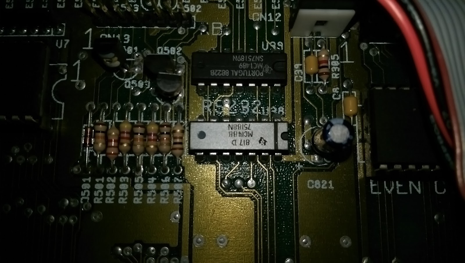
Next, lets plug this baby in. The screen turns white then almost instantly shows solid green. That's not good. It means that there's a problem with the chip RAM but could mean that it's the RAM that's faulty or any of the components between the RAM, CPU, ROM and custom chips... This will take a bit of work. 

OK, so now we inspect the board a lot more closely. I cleaned off as much of the green corrosion as I could, partly by scraping with a scalpel and partly by using isopropyl alcohol. Not as good as lemon juice but it did the job for what I needed. Next, a lot closer look at the tracks that are in the firing line:


There's one definite break (possibly more)

Close up of 4th pad down on top picture - definitely unhappy


A clean break - no copper left here at all

By using the continuity function on a multimeter I confirmed that there were two traces that definitely had problems. These were from the 'south' end of R101 to the via and from the 'south' end of R112 to the via. As it turns out, there was a third issue from the 'south' side of E102, as it runs past the leg of the EVIL KILLER FROM HELL - er I mean battery. 

For the resistor R101, I could not find where the break was. It was most likely that the trace had multiple tiny breaks, making it impossible to just use a sliver of wire as a track repair. In the end, I installed a jumper from R101 to the via. 

For the resistor R112, things were a bit more straightforward. I used a stripped piece of 30awg wrapping wire, about 6mm long and bent into the right shape to bridge the gap from the track to the via.

Finally, I used a straight piece of the same wire, again about 6mm long, to repair the straight trace that had been damaged next to the battery leg.

The results look like this:

Wire added from broken track to via - jumper visible back to R101

Connection to R101 - not the neatest but it's connected now

Track repair next to the battery leg (battery removed)

Before I could test it I realised that the trapdoor connector had suffered badly too at the hands of the evil battery. The pins had corroded badly and there was nothing I could do to save them. I had to remove the entire connector. :(  Fortunately, they are available new. Yay! :)

Connector still attached but looking poorly...

Connector partly removed - not looking any better

Pins cleaned up to illustrate the damage batteries can cause
So, with all this done, time to plug it in and see if there is any improvement. Why, yes, Yes there is. :) 

Another A500+ saved from the bin

There is still a lot to do on this but the worst of the problems are out of the way. Stuff that needs doing:
  • Test the whole thing
    • Floppy drive
    • Sound
    • Keyboard
    • All ports
  • Replace the trapdoor connector
  • Buy a case, keyboard and floppy...(remember I only bought a faulty motherboard!)
I will update you all soon once I've carried out more tests, but so far, it's looking good.


Monday, April 18, 2016

Amiga Audio Issues - Part 3


So, the MC1488 chips have arrived. The one in the A500 is actually an MC1488N made by Texas Instruments whereas the ones I have here are MC1488P made by Motorola. There is no difference in the chips at all. In fact, my A500+ actually has an MC1488P.

MC1488P x 5

Having done a lot more reading I understand what the MC1488 is doing in this context. It is normally used in changing TTL voltages to RS232 voltages for serial communications. They contain four 'drivers', a driver being the conversion from TTL voltages to RS232. The MC1489 chip which sits above the MC1488 on the motherboard contains four 'receivers', which convert RS232 back to TTL voltages. In this particular instance, the first input appears is being used as a 'NOT' gate to change the 0v to 5(ish)v from the CIA into a more meaty +12v to -9v.

I won't go into any more detail, partly because it could become very technical but mostly because I don't fully understand it all. Suffice it to say that when the MC1488 has 0v on pin 2 there should be 12v on pin 3 and when there's 5v on pin 2 there should be -9v on pin 3. Given that my MC1488 has 12v - or thereabouts - on pin 3 no matter what the voltage on pin 2, this leads me to believe that there is an open circuit in the chip, hence, replace the chip. :)

So, tops off again chaps...

Unfortunately my phone camera failed miserably and didn't take pictures of the process of me getting the chip off the board. :(  Basically, it involved cutting through the legs on one side of the chip - carefully - then bending up the chip to make it easier to do the same to the other side. A few minutes later, with the help of some solder wick and a pair of good quality tweezers and the chip and it's legs are gone.

The dead MC1488 RS232 line driver chip

This chip was silver for some reason. It's the only time I've seen one like this. In my A500+ it's black and all of the pictures of the various A500 motherboards on the Big Book of Amiga Hardware website show it as black too. Maybe it was special? Either way, it's dead.

Awaiting pin removal

I cleaned the old solder off with solder wick and then cleaned the surface with isopropyl alcohol with some cotton buds. Finally, I used a bit more alcohol and an old toothbrush to make sure no debris or other junk was left nearby.

New MC1488P installed and ready for action

Once the chip was inserted it was a two minute job to solder the fourteen pins. Far easier than Agnus.. Once again, when I'd finished I cleaned the board with some isopropyl alcohol and cotton buds, followed by a final scrub with the toothbrush.

Let's get this sucker tested!

I plugged in the floppy drive, power cable, monochrome composite output (who wants to mess with an A520 at this point? Not me.) and audio out left and right to my PC speakers. The A500 booted without any problem but then guru'ed when I tried to run OctaMED. Like a numpty I had forgotten to put the 512kb expansion in too. OctaMED won't run in 512kb...

Testing - this time with 1Mb.
Take 2.

It worked flawlessly. The difference in sound is now quite distinct with a definite treble and white noise that wasn't there before. Switching the filter on restores the 'muffled' sound, just as intended. Another repair successfully completed. :)

Success! The filter is working!


Thursday, April 14, 2016

Amiga Audio Issues - Part 2 - A Diversion

So, while I was trying to diagnose the issue with the MC1488 I managed to drop the multimeter probes just before I finished and shorted something. The Amiga froze. No big deal. Just restart it. But it didn't restart, instead I was left looking at a dark grey screen.

Dodgy MC1488 Chip (the silver one)

Ah - Dark Grey Screen on Bootup
Don't panic! Stay calm!

No worries. Just pop the top off again, press all the chips into place (the ROM and Agnus made satisfying creaking noises - normally an indication that they're not in properly) and try again. This was the result:


ARRGHHH!!! PANIC!!! ARGHHHHH! I've killed it!!

After a stiff drink and a lie down I came back to it and tried to reason things out. The screen, although rolling, is definitely green. This normally indicates an issue with the chip RAM. That was, however, a bit unlikely since I had been nowhere near that part of the board and it would be a big coincidence that a RAM chip died at that very moment. But I had read somewhere that problems with Agnus could also, in some situations, cause a similar fault.

With a spare Agnus I managed to improve things slightly. But only slightly since I now had a solid bright green screen or random coloured pixels.

Our situation has not improved...
Maybe it was the chip RAM at fault. I had a RAM chip of the same type in my box so I placed it over each existing chip and turned on the Amiga to see if the green screen would go away. Sadly this made no difference.

Appeals to the Amiga group on Facebook (hi guys!) resulted in many suggestions but the one that kept cropping up was to re-seat Agnus. But there was no point since Agnus was as far into the socket as I could push her....(can you see where this is going?)

Out of curiosity, I removed Agnus and then pushed the chip into the socket but only just so the top of the chip was proud of the socket. Sure enough, the Amiga burst back into life. The socket was borked.

In this case, ebay is you friend. Four new sockets delivered for a couple of quid.


Cue montage of me sweating over a steaming motherboard, wiping my brow, looking at schematics, reaching for tools, slurping tea etc. Pictures of my removing the socket are not included to protect the sensitive..

Socket Removed
New Socket Inserted 
Chips Re-installed
If you have a go at this type of repair, and if I can do it then anyone can, here's a couple of tips. Firstly, get yourself some de-soldering braid and a de-solder pump. I had the braid but not the pump so to get the old solder out of the holes for the socket I had to use a pin. Using the soldering iron I melted the solder and pushed the pin through the hole. The solder got dragged through the hole by the pin then cooled down, to be removed with a quick wipe of the iron. 84 times. Get yourself a de-soldering pump. Do it. NOW.

With a new socket, both of the Agnus chips I have now work without any issues so this socket repair is done. :)

Repaired and fully operational.